


BeagleBone DVI-D with
Audio Cape
System Reference Manual
Revision A1
Page 23 of 28
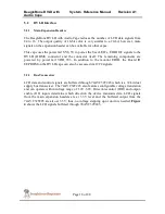
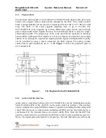
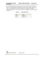
AM335x. Data is transmitted or received by the McASP serializers. Figure 8 shows the
Audio Serial Bus Interface between the codec and the microprocessor.
Figure 8.
Audio Serial Bus Interface
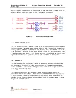
5.3.5
TLV320AIC3106 Codec
The TLV320AIC3106 codec requires a hardware reset after power-up in order to respond
properly to register changes in values. Its reset signal is active low and tied to the system
reset signal SYS_RESETn. The TLV320AIC3106 on the BeagleBone DVI-D with Audio
Cape is digitally controlled via I2C serial interface. This I2C protocol supports both
standard and fast modes and has a 7-bit address of 0011011. An external oscillator is used
to provide a 12MHz clock signal to the master clock input (MCLK) of the codec.
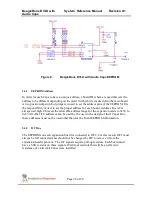
5.4
EEPROM
The BeagleBone DVI-D with Audio Cape has an EEPROM containing information that
will allow the SW to identify the board and to configure the expansion headers pins as
needed. EEPROMs are required for all Capes sold in order for them to operate correctly
when plugged in the BeagleBone.
The EEPROM used on this cape is the same one as is used on the BeagleBone, a
CAT24C256. The CAT24C256 is a 256 kb Serial CMOS EEPROM, internally organized
as 32,768 words of 8 bits each. It features a 64-byte page write buffer and supports the
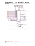
Standard (100 kHz), Fast (400 kHz) and Fast-Plus (1 MHz) I2C protocol. Figure 9 is the
design of the EEPROM circuit.


