


C-14
“Oil-Less” Scroll Laboratory Air
4107 9006 25.11
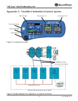
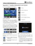
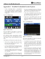
Appendix C: TotalAlert Embedded Control System
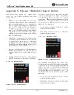
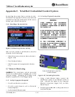
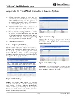
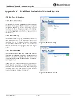
By selecting the activity that is overdue (in red),
the detail screen appears for that service item and
provides the necessary information for the service
activity: part number, description.
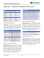
C.6.3 Resetting a Service Activity
Figure C.26 Resetting a Service Activity
After a service activity is performed, to reset the
schedule, do the following:
• Select the service activity on the touchscreen
(Figure C.26).
• Press the Reset button.
• Enter the password (as explained in Section
C.4).
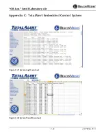
C.7 Remote Monitoring
CAUTION:
The information systems personnel
should be notifi ed before changing any of the
network settings. Changing the settings could
keep the equipment from working properly.
C.7.1 Set Up: Equipment Required
• PC with an Ethernet connection
• PC with a web browser, such as Microsoft
Internet Explorer
• Cat5 or better Ethernet cable
C.7.2 Set Up: Physical Connection
WARNING:
ONLY CONNECT THE CUSTOMER
NETWORK TO THE CUSTOMER
ETHERNET CONNECTION AS SHOWN
IN FIGURE C.27.
DO NOT UNPLUG EXISTING ETHERNET
CABLES USED FOR THE INTERNAL
CONNECTIONS. DO NOT ATTEMPT
TO REMOVE ETHERNET SECURITY
PROTECTORS TO USE FOR CUSTOMER
ETHERNET CONNECTION.
IF THE CUSTOMER ETHERNET IS
PLACED IN AN INTERNAL ETHERNET
CONNECTION, THE INTERNAL
ETHERNET FUNCTIONALITY WILL NOT
PERFORM AS DESIGNED.
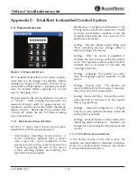
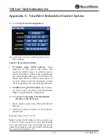
Customer Ethernet Connection
on PCB3 Master
Figure C.27 Connecting the cable
1. Using a Cat5 Ethernet cable, connect the
medical air system to an Ethernet switch or
hub. Connect the cable to the Customer
Ethernet Connection (Figure C.27) on PCB3
Master board.
2. Verify the green LINK LED on the printed circuit
board illuminates.


