


10 Troubleshooting (Continued)
1
Troubleshooting Procedures
PROBLEM
PROBABLE CAUSE
CORRECTIVE ACTION
Door will not open (Continued).
2. Wizard not detecting traf
fi
c.
3. Faulty wiring between sensor and door
control.
4. Faulty door control.
2. Walk in and out of Wizard detection area, if
red LED does not illuminate check:
a. Power supply for Wizard: 12 to 24 VAC
/ VDC: -5% to +10%
b. Check SMR setting on each Wizard.
The SMR should be disabled unless
system is being used with BEA’s Door
Control Unit (DCU).
c. Check Relay Con
fi
guration for each
Wizard.
3. Remove all sensor inputs from the door
control. Jumper the common and activate
terminals of the door control. If door does
not open, fault lies within door control or
motor. Refer to manufacturer’s manual for
further troubleshooting. If door opens, fault
lies with sensors or related wiring.
4. Refer to Step 3.
Door keeps recycling open.
1. Wizard is seeing door.
2. Wizard is seeing movement from unwanted
objects.
3. Vibration is triggering the Wizard.
1. Observe LED status on each Wizard.
Green LED indicates motion detection, red
LED indicates presence. If LED’s are on,
make sensor adjustments as necessary
to eliminate unwanted detection. Check
angle, sensitivity, and immunity for
presence and motion.
2. Check for moving objects in the path of
detection, such as posters, banners, etc.
3. Locate source of vibration and correct as
necessary.
Wizard will not respond to remote control.
1. Batteries in remote are dead or are
installed improperly.
1. Ensure batteries are installed correctly.
Replace batteries: AAA 1.5 volt.
Wizard will not unlock when access code is
entered.
1. Improper code being entered.
1. Reset code to the default value of 0000 by
performing the following:
a. Cut and restore power supply. No code
is required to unlock during the
fi
rst
minute after powering. Reset code prior
to locking.
Red LED is
fl
ashing rapidly after attempting
setup.
1. Detection
fi
eld was violated during setup of
the Wizard.
1. Launch a new setup and insure that the
detection
fi
eld remains all clear until setup
is complete.
2. Wizard may be seeing the door as it is
closing. Adjust infrared curtain and launch
a new setup.
Wizard will not detect – door stays open.
1. Improper SMR setting.
1. If the Wizard is NOT being used with a
BEA DCU, set SMR to a value of 0.
12 Company Contact
Do not leave problems unresolved. If a satisfactory solution cannot be achieved after troubleshooting a problem, please
call BEA, Inc. If you must wait for the following workday to call B.E.A., leave the door inoperable until satisfactory
repairs can be made. Never sacri
fi
ce the safe operation of the automatic door or gate for an incomplete solution.
The following numbers can be called 24 hours a day, 7 days a week. For more information, visit www.beasensors.com.
West:
South-East:
US and Canada:
1-888-419-2564
1-800-407-4545
1-866-249-7937
Mid-West:
North-East:
Canada:
1-888-308-8843
1-866-836-1863
1-866-836-1863
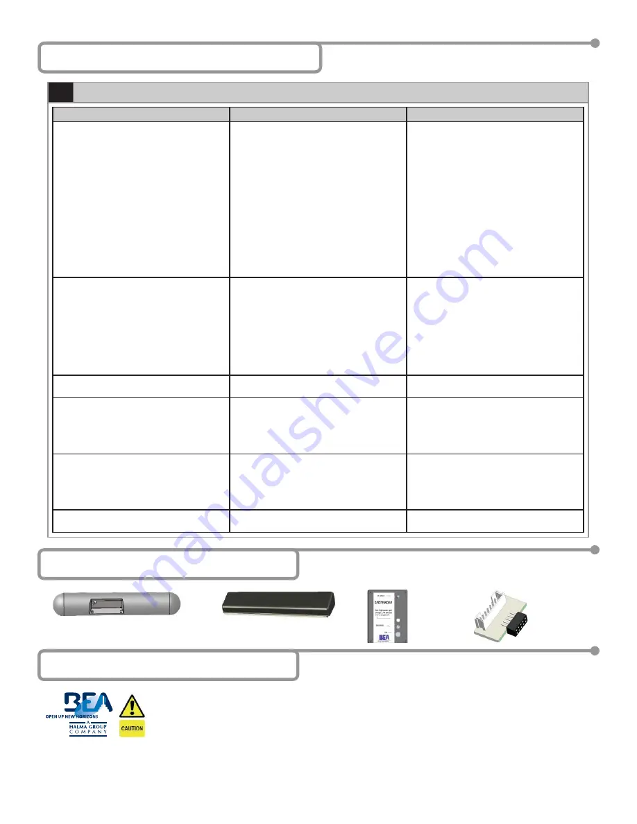
11 Accessories
Ceiling Adapter
10WCA
Universal Rain Cover
10URC
Spot
fi
nder
10SPOT
Cable Adapter
20.5048
75.5122.05
20070427
Page
9
of
13
OBSOLETE


