


8 Manual Set Up Without Remote
1
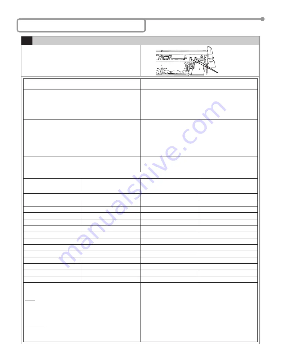
Manual Set Up
Set up of the Wizard may be accomplished by the use of two Wizard
mounted programming buttons. The procedures below indicate how to
program using these buttons.
To begin programming
:
Brie
fl
y press the right button and move away from the sensing
patterns.
To reset the unit to factory defaults including access code
:
Press and hold both buttons simultaneously until both Red and Green
LEDs
fl
ash alternately.
To customize the settings from factory defaults
:
To enter the customizing mode
: Press the right button until the LED
fl
ashes and then release.
To return to standard mode
: Press the right button again until the
LED stops
fl
ashing and then release.
Customizing Mode
:
• The Red LED light indicates the number for the parameter being
altered (1
fl
ash = parameter #1).
• The Green LED light indicates the value for the parameter being
altered (1
fl
ash means value = 1).
• The Right Button enables selection of the parameter number being
altered (+1 for each press).
• The Left Button enables alteration of the parameter (+1 for each
press).
Helpful Hint
:
When the sensor is wired correctly pressing and holding the left
button will result in disconnecting all outputs from that sensor,
allowing the door to close, if no other devices are being activated.
PARAMETER NUMBER
(Altered by the right button and
confi rmed by RED LED)
PARAMETER
VALUES
(Altered by the left button and
confi rmed by GREEN LED)
DEFAULT VALUE
1
Radar Sensitivity
0-9
7
2
Relay hold time
0-9
0
3
Output con
fi
guration
1-4
4
4
Auto-learn presence sensing
0-9
0
5
Detection mode
1-4
3
6
Microwave Immunity
1-9
3
7
IR Immunity
1-3
2
8
Not Used
Displays 8 Orange Flashes
Displays 8 Orange Flashes
9
SMR mode
0-1
0
10
IR curtain
1-3
3
11
Secondary Sensitivity
0-9
0
12
Height & Frequency
1-4
1
13
Output Re-Direction
0-2
0
14
Door Control Function
1-3
1
EXAMPLE: Change radar sensitivity from 7 to 9 and set hold time to
4 seconds:
NOTE: When the highest value for the parameter has been reached,
the value will “roll over” to its lowest value (e.g. for radar
mode: 1, 2, 3, then 1, 2, …).
The sensor automatically returns to standard mode if neither
button has been pressed for one minute.
REQUIRED: If the IR frequency has been manually changed, to
prevent the sensors from being in permanent detection,
momentarily depress the right program button to launch
an assisted setup.
Press the right button for 2 seconds, you will enter the customizing
mode:
• The green LED
fl
ashes once (parameter 1)
• The red LED
fl
ashes 7 times (sensitivity = 7)
• Press the left button twice to move from
sensitivity = 7 to sensitivity = 9
Press the right button once to move to Parameter 2 (relay hold time):
• The green LED
fl
ashes twice (parameter 2)
• The red LED does not
fl
ash (hold time = 0 seconds)
• Press the left button four times to move from hold time = 0 to hold
time = 4 seconds
Program Buttons
75.5122.05
20070427
Page
7
of
13
OBSOLETE


