background image

12     

BE-AGMZXXX USER MANUAL

EVERY 50 HOURS OF WORK

• Check the correct tension of the driving belt.
• Check that all bolts and nuts are tightened.
• Check the cutters/hammers for wear.
• Check the over-gear unit oil level through plug A (Picture 5).

EVERY 500 HOURS OF WORK

• Check that all bolts and nuts are tightened.
• Change oil in the over-gear unit.

EVERY 1000 HOURS OF WORK

• Replace the driving belt.

GEARBOX MAINTENANCE

• The oil should be drained out and replaced after the first 50 hours of operation.
• Then the oil should be changed every 250 hours, or at least once a year.
• Drain oil form the gearbox thoroughly. Check and clean it. Fill with new gear oil up to the dedicated oil 

level.

• The draining procedure is as follows: remove the draining bolt under the gearbox, so that the oil drains off. 

After the oil is drained out, put the plug back and fill with gear oil up to the dedicated oil level.

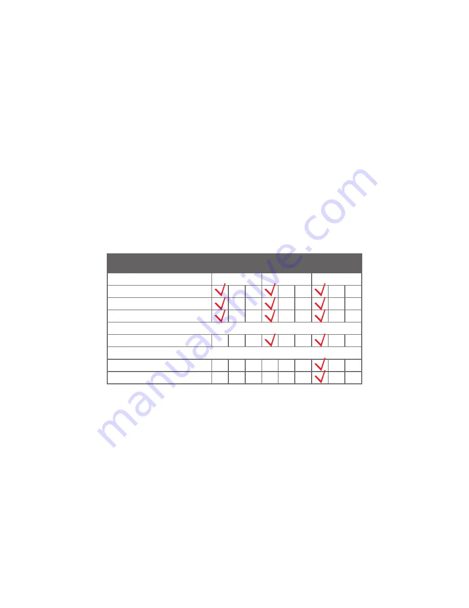
Maintenance Checklis

t

8HRS/Daily

Lubricate PTO Shaft

Check Gear Box Oil Level

Lubricate Caster Wheels

Clean Machine

Lubricate & Clean PTO SHaft Cover

Lubricate Blade Spindle

50HRS/Weekly

Annually

PTO SHAFT MAINTENANCE

The PTO shaft is designed to telescope to allow for dimensional changes as the machine goes through its 

operating range. A tubular guard encloses the driving components and is designed to turn relative to the 

driving components. The shaft should telescope easily and the guard turn freely on the shaft at all times. 
Annual disassembly, cleaning and lubrication is recommended to ensure that all components function as 

intended.
To maintain the shaft, follow this procedure:
1.  Remove the shaft from the machine.
2.  Pull shaft apart.
3.  Use a screwdriver to pry the tabs out of the sleeves on each end.
4.  Pull the shaft out of the plastic tubular guard.
5.  Use a solvent to clean the male and female portions of the telescoping ends.
6.  Apply a light coat of grease to each end.
7.  Clean the grooves on each end where the tabs are located.
8.  Apply a light coat of grease to each groove.
9.  Insert the shaft into its respective guard and align the slots with the groove.

Summary of Contents for BE-AGMZ Series

Page 1: ...PURCHASE DATE MODEL NO SERIAL NUMBER DEALER FLAIL MOWER BE AGMZXXX OPERATIONS PARTS MANUAL FOR MODELS BE AGMZ200 BE AGMZ220 BE AGMZ240 ...

Page 2: ...TABLE OF CONTENTS 3 INTRODUCTION SAFETY 7 ASSEMBLY 10 TRANSPORT 11 STORAGE MAINTENANCE 14 EXPLODED VIEWS PARTS LISTS ...

Page 3: ...S The safety labels and the information on the machine listed in the following table must be necessarily read and respected failure to follow these warnings can cause death or sever injuries Make sure that the labels are always present and legible should this not be the case contact your nearest dealer to replace the missing or illegible ones 1 WARNING The operations of regulations and maintenance...

Page 4: ...NG Do not stand between the tractor and the machine 10 DANGER of crash for the legs Keep proper distance 11 DANGER of squashing shearing of the hands 12 WARNING Hot surface Keep the proper distance 13 WARNING Do not remove or open the protection carters until the belts are completely still 14 WARNING Danger of squashing Do not stand in the move and side shifting zone of the machine 15 WARNING For ...

Page 5: ...nd or operating with the wrong size tractor can cause mower component damage and equipment failure resulting in possible serious injury or death SAFETY IN THE WORKPLACE Most of the accidents which take place while the operator is using the machine or the equipment or during their maintenance or repair are caused by a lack of compliance with basic safety precautions If it is necessary therefore to ...

Page 6: ...all shields in place and in good operational condition The operator must be familiar with the mower and tractor and all associated safety practices before operating the mower and tractor GENERAL SAFETY When working or during the maintenance activities it is necessary to remember The labels and stickers providing instructions and pointing out the dangers must not be removed hidden or made illegible...

Page 7: ...efully the instruction manuals of the tractor and PTO shaft manufacturers All AG Flail Mowers have been manufactured to be attached to any tractor provided with hydraulic and universal 3 Point hitch The tractor used to operate the mower must have the power capacity and required equipment to safely operate the mower Operating the mower on improperly sized and equipped tractors may cause tractor and...

Page 8: ...the safety guards cover the PTO shaft throughout its extension When attaching the mower input driveline to the tractor PTO be sure that the connecting yoke spring activated locking collar slides freely and the locking balls are seated securely in the groove on the tractor PTO shaft A driveline not attached correctly to the tractor PTO shaft could come loose and result in personal injury and damage...

Page 9: ... top link Lower the three point linkage to its lowest position With the roller at the rear in contact with the ground adjust the length of the top link so that the lower edge at the side of the flail mower is parallel with the ground Rotate the blade drum by hand so that a row of blades hangs vertically towards the ground Measure the clearance between the bottom of the extended blades and the grou...

Page 10: ...f the material to be cut for efficient mower performance it must be between 2 and 5 MPH The power take o_ speed must be 1000 RPM maximum Operate the mower at its full rated PTO speed to maintain blade speed for a clean cut DANGER Do not exceed the rated PTO speed for the implement Excessive PTO speeds can cause driveline or blade failures resulting in serious injury or death ROAD TRANSPORT Extreme...

Page 11: ...eration to extend life and performances of any agricultural vehicle taking care of the machine grants you not only a good work execution but also a longer life of the whole equipment and a greater safety in the workplace The operating times indicated in this manual have just an informative character and are referred to normal conditions of use they can thus undergo variations according to the type...

Page 12: ... PTO Shaft Check Gear Box Oil Level Lubricate Caster Wheels Clean Machine Lubricate Clean PTO SHaft Cover Lubricate Blade Spindle 50HRS Weekly Annually PTO SHAFT MAINTENANCE The PTO shaft is designed to telescope to allow for dimensional changes as the machine goes through its operating range A tubular guard encloses the driving components and is designed to turn relative to the driving components...

Page 13: ...s through the slots and seat in the groove 11 Check that each guard turns freely on the shaft 12 Assemble the shaft 13 Check that the shaft telescopes easily 14 Replace any components that are damaged or worn 15 Install the shaft on the machine ...

Page 14: ...14 BE AGMZXXX USER MANUAL EXPLODED VIEW PARTS LIST ...

Page 15: ... 022 Plate 1 22 GB893 1 86 90 Cir Clip 2 23 GB13871 94 40x90x10 Oil Seal 2 24 GB T276 94 6308 Bearing 2 25 GB894 1 86 40 Cir Clip 2 26 1 EFAG200 017 200 Roller 1 REF PART NUM DESCRIPTION QTY 26 2 EFAG220 017 220 Roller 1 26 3 EFAG240 017 240 Roller 1 27 4J 220H 136 Big Pulley 1 28 EFAG140 020 Plate 1 29 GB6184 86 M16 Locking Nut 6 30 GB97 1 85 16 Washer 6 31 GB5783 86 M16x45 Bolt 4 32 GB5783 86 M1...

Page 16: ...Bearing Seat 1 6 GB894 1 86 45 Cir Clip 1 7 GB T281 94 1309 Bearing 2 8 GB893 1 86 100 Cir Clip 1 9 GB13871 94 65x100x10 Oil Seal 2 10 1 VM200 017 200 Axle 1 10 2 VM220 017 220 Axle 1 10 3 VM240 017 240 Axle 1 11 GB6184 86 M16 Nut 20 12 EFAG140 103 Hammer 20 13 EFAG140 190 M16x1 5x92 Bolt 20 14 GB13871 94 45x80x8 Oil Seal 1 15 VM190 111 Bearing Seat 1 16 EFAG140 023 Pipe 1 ...

Page 17: ...1 86 33 Cir Clip 1 4 G2 150 110 Sleeve 1 5 GB1096 79 A12x50 Key 1 6 VM190 109 Transmit Shaft 1 7 GB T278 94 6308ZZ Bearing 1 8 GB893 1 86 90 Cir Clip 1 9 GB13871 94 40x90x10 Oil Seal 1 10 ZBT 32001 3 87 ZG3 8 19 Bolt 1 11 FM120 00 199A Bolt 1 12 VM190 020 PTO Cover 1 13 GB70 1 85 M12x35 Bolt 4 14 GB93 87 12 Washer 4 15 AGM200 130 Gasket 1 ...

Page 18: ... C01 1 8 GB894 1 42 A 1 9 GB276 6308 1 10 TZDP 90 79 0 4 90x79x0 4 2 11 GB893 1 90 A 1 12 NFG RCA 90x10 90X10 2 13 CBW 00 011B ZG3 8 1 REF PART NUM DESCRIPTION QTY 14 AG20 01 C02 311 1 15 AG20 01 C03 311 1 16 ZBT32001 3 ZG3 8 19 3 17 GB96 10 8 18 GB5783 M10x25 8 19 CFW 35x90x10 FB 1 20 TZDP 100 89 0 4 100x89x0 4 2 21 GB276 6407 1 22 AG20 01 C04 1 23 AG14 01 C07 3 24 AG14 01 C06 3 25 AG14 01 C05 1 ...

Page 19: ...g 1 10 GB5782 86 M24x140 Bolt 2 11 AGMZ 200 011 Suspension Bracket 1 12 SF 2 65x70x40 Bearing 4 13 VM190 164 Rail Guide 1 REF PART NUM DESCRIPTION QTY 14 AGM200 014 Cylinder 1 15 GB1152 89 M6 Grease Nipple 2 16 EFAG140 010 Pipe 2 17 GB3451 83 12 Bronze Washer 4 18 GB3451 83 M12x1 25 Bolt 2 19 EFAGL125 103 Pin 2 20 GB93 87 8 Washer 2 21 GB5783 86 M8x16 Bolt 2 22 GB6184 86 M12 Nut 4 23 GB97 1 85 12 ...

Page 20: ...20 BE AGMZXXX USER MANUAL PHONE 604 850 7770 FAX 604 850 7774 TOLL FREE PHONE 1 877 588 3311 TOLL FREE FAX 1 800 665 7334 BRABEREQ COM WGSALES BRABEREQ COM ...

Reviews: