background image

More information

l

Removing air bubbles (page 29)

l

Changing the sheath filter (page 43)

l

Cleaning or replacing the sheath gasket (page 49)

Removing air bubbles

Introduction

This topic describes how to remove trapped air bubbles in the sheath filter and the sheath line. Air bubbles can
occasionally dislodge and pass through the flow cell, resulting in inaccurate data.

Note:

Perform this activity every time the sheath tank is refilled.

Procedure

To remove air bubbles:

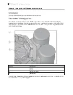
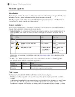
1. Check the sheath filter for trapped air bubbles.

1

2

3

Number

Components

1

Cytometer fluid line (roller clamp not visible)

2

Vent fitting

3

Vent line

Chapter 3  Cytometer setup

29

Summary of Contents for FACSymphony A1 Flow

Page 1: ...FACSymphony A1 Flow Cytometer User s Guide 23 23437 01 2022 07 For Research Use Only ...

Page 2: ...NJ 08855 1327 USA Laser safety information Class 1 Laser Product Regulatory information For Research Use Only Not for use in diagnostic or therapeutic procedures FCC information WARNING Changes or modifications to this unit not expressly approved by the party responsible for compliance could void the user s authority to operate the equipment NOTICE This equipment has been tested and found to compl...

Page 3: ...th and waste tanks 21 Optics 22 Workstation 23 3 CYTOMETER SETUP 25 Starting the cytometer and computer 26 Preparing the sheath tank 27 Removing air bubbles 29 Preparing the waste tank 30 Preparing the fluidics 32 About the optical filters and mirrors 34 Custom configurations and baselines 35 4 MAINTENANCE 37 Maintenance overview 38 Cleaning the fluidics 39 Shutting down the cytometer 40 Flushing ...

Page 4: ...nalysis workflow 68 Preparing the workspace 68 Recording data 69 Analyzing data 71 Reusing an analysis 75 7 TECHNICAL OVERVIEW 77 About fluidics 78 About optics 79 About electronics 84 8 TROUBLESHOOTING 89 Cytometer troubleshooting 90 Electronics troubleshooting 95 9 DETECTOR ARRAY CONFIGURATIONS 97 Fluorescence spectra 98 About configuration maps 99 About configurations 100 Base configuration pol...

Page 5: ...11 SUPPLIES AND CONSUMABLES 117 Ordering information 118 Beads 118 Reagents 118 Equipment 119 INDEX 121 Contents 5 ...

Page 6: ......

Page 7: ...1 About this guide This chapter covers the following topics l What this guide covers page 8 l Conventions page 8 l About the BD FACSymphony A1 documentation page 8 l Instrument technical support page 9 ...

Page 8: ...o potential hazards Safety symbols Symbol Meaning Caution Identifies a hazard or unsafe practice that could result in data loss material damage minor injury severe injury or death Biological hazard Electrical hazard Laser hazard About the BD FACSymphony A1 documentation Introduction This topic describes the documentation available with the BD FACSymphony A1 flow cytometer Documentation USB Card Th...

Page 9: ...rument technical support Introduction This topic describes how to get technical assistance Contacting technical support If technical assistance is required contact your local BD Biosciences customer support representative or supplier When contacting BD Biosciences have the following information available l Product name part number and serial number l Version of BD FACSDiva software you are using l...

Page 10: ...This page intentionally left blank ...

Page 11: ...This chapter covers the following topics l System overview page 12 l Cytometer overview page 13 l Control panel page 15 l Fluidics system page 16 l Sheath and waste tanks page 21 l Optics page 22 l Workstation page 23 ...

Page 12: ... HTS Each component is described in detail in the following sections In addition the BD Small Particle Detector SPD is an optional side scatter detector optimized to improve resolution of small particles such as extracellular vesicles For more information see Small Particle Detector page 105 TM 3 2 1 Number Components 1 Sheath and waste tanks 2 BD FACSymphony A1 flow cytometer 3 Computer workstati...

Page 13: ...ting fluorescence signals into electronic signals Cytometer electronics convert these signals into digital data Components The following figures show the main components on the front and right side of the BD FACSymphony A1 flow cytometer The descriptions are listed in the tables TM 5 4 3 2 1 Number Component 1 Heat ventilation slots top 2 Control panel 3 Sample injection port SIP 4 Heat ventilatio...

Page 14: ... laser detector array access panel 2 Power button 3 Electrical plug 4 Fluidic sensor ports 5 Air and fluidic ports 6 USB port for Small Particle Detector to workstation Do not place any objects on top of the instrument Blocking the ventilation may cause the instrument to overheat Do not place liquids on top of the instrument Any spill of liquid into the ventilation openings could cause electrical ...

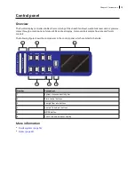
Page 15: ...rols sample flow rate and fluidic controls The following figure shows the components in the control panel which are listed in the table 6 5 4 3 2 1 Number Component 1 System status and activity bar 2 Fluid control buttons 3 Sample flow rate buttons 4 Sample fine adjust buttons 5 MODE button 6 Touch screen and status display More information l Fluidics system page 16 l Optics page 22 Chapter 2 Intr...

Page 16: ...ly full Red Take immediate action l Empty waste tank l Fill sheath tank l Check air pressure Sheath empty and or waste full Air pressure is out of specification System status is also displayed on the Status screen See Status screen page 18 for a description of the Status screen l Activity Shows whether the cytometer power is on and the status of acquisition The following table describes the indica...

Page 17: ... prevent bubble formation or entrapment At completion the cytometer switches to standby mode Sample flow rate control The three flow rate buttons LOW MED HIGH control the sample rate through the flow cell The three fluidic control buttons RUN STANDBY PRIME enable you to control the sample acquisition rate 2 1 Number Component 1 Sample flow rate buttons 2 Sample fine adjust buttons When sample adju...

Page 18: ...l set point is 250 The last value persists even after cytometer shutdown 2 Sheath Level Shows range from 0 to 100 The display line decreases from top to bottom in sequences of 20 from full level System status turns yellow at 20 and red at 0 3 Waste Level Shows range from 0 empty to 100 full The display line increases from bottom to top in sequences of 20 System status turns yellow at 80 and red at...

Page 19: ...own to the Off position turns the air pressure warning off Fluidic alarms and the Mode button The fluidic alarms are triggered by the waste and sheath fluid levels in the tanks and by low or high sheath tank air pressure levels The alarms sound when the waste tank is nearly 100 full and the sheath tank is empty The fluidic alarms and system status will also show warnings when you start up the cyto...

Page 20: ... vacuum is on when the arm is positioned to the side and off when the arm is centered Note If a sample tube is left on the SIP with the tube support arm to the side vacuum on the sample will be aspirated into the waste container Precautions when using the HTS option When using the BD FACSymphony A1 flow cytometer with the HTS ensure that the HTS is completely pushed into the operating position bef...

Page 21: ...n line interchangeable filter that prevents small particles from entering the sheath fluid lines An alarm sounds when the tank is empty Do not fill the sheath tank to its maximum capacity When an overfull tank is pressurized erratic cytometer performance can result Waste tank The waste tank has a capacity of 10 L An alarm sounds when the tank is full Cable management Arrange the cables air lines a...

Page 22: ...rs Optical filters attenuate light or help direct it to the appropriate detectors The name and spectral characteristics of each filter appear on its holder There are two types of optical filters in the BD FACSymphony A1 l Longpass dichroic filters LPs Transmit wavelengths at or longer than the specified value and reflect all light below the specified wavelength l Bandpass filters BPs Pass a narrow...

Page 23: ...an the PMTs A photodiode is used to detect the stronger forward scatter FSC signal More information l Optical filter theory page 80 l About configurations page 100 Workstation Introduction This topic describes the components of the BD FACSymphony A1 workstation Workstation components Acquisition analysis and most instrument functions are controlled by the BD FACSymphony A1 workstation It includes ...

Page 24: ...This page intentionally left blank ...
Page 25: ...ing the cytometer and computer page 26 l Preparing the sheath tank page 27 l Removing air bubbles page 29 l Preparing the waste tank page 30 l Preparing the fluidics page 32 l About the optical filters and mirrors page 34 l Custom configurations and baselines page 35 ...

Page 26: ... the computer and log in to Windows Note You can turn on the power to the flow cytometer and the workstation in any order 3 Start BD FACSDiva software by double clicking the shortcut on the desktop and log in to the software 4 Check the Cytometer window in BD FACSDiva software to ensure that the cytometer is connected to the workstation The cytometer connects automatically While connecting the mes...

Page 27: ...for more information When to check the sheath tank Check the fluid levels in the sheath tank every time you use the cytometer This ensures that you do not run out of sheath fluid during an experiment Sheath tank components 7 6 5 4 3 2 1 Number Component 1 Cap handle 2 Filter assembly 3 Sheath fluid line blue to sheath tank 4 Air line green 5 Alarm sensor 6 Clamp knob Chapter 3 Cytometer setup 27 ...

Page 28: ...e sheath tank lid Unscrew the clamp knob and push down to loosen if necessary Tilt the cap to the side to remove it from the tank 6 Add up to 10 L of sheath fluid such as BD FACSFlow solution to the sheath tank Note 10 L will reach the interior line on the sheath tank Do not fill the sheath tank further 7 Replace the sheath tank lid 8 Make sure the gasket on the inside lip of the sheath lid is sea...

Page 29: ...bbles in the sheath filter and the sheath line Air bubbles can occasionally dislodge and pass through the flow cell resulting in inaccurate data Note Perform this activity every time the sheath tank is refilled Procedure To remove air bubbles 1 Check the sheath filter for trapped air bubbles 1 2 3 Number Components 1 Cytometer fluid line roller clamp not visible 2 Vent fitting 3 Vent line Chapter ...

Page 30: ...nterconnect if necessary to bleed off any air in the line Collect any excess fluid in a waste container Note The roller clamp can be found close to the fluidics ports of the cytometer 8 Close the roller clamp Preparing the waste tank Introduction This topic describes how to prepare the waste tank Prevent waste overflow by emptying the waste tank daily or whenever the system status indicator turns ...

Page 31: ...ytometer in standby mode before disconnecting the waste tank to avoid leakage of biohazardous waste l Always disconnect the waste tank from the cytometer before you empty it Wait at least 30 seconds for pressure to dissipate before you remove the waste cap or sensor l Expose waste tank contents to bleach 10 of total volume for 30 minutes before disposal l Do not wet the waste tank cap If wet the f...

Page 32: ...chanics to prevent injury 5 Add approximately 1 L of bleach to the waste tank and close it Reattach the moisture trap and lid 6 Reconnect the orange waste tubing and make sure it is not kinked 7 Reconnect the black alarm sensor line Note Make sure the alarm sensor socket is off the ground by looping the line through the handle of the waste tank Preparing the fluidics Introduction This topic descri...

Page 33: ...nnels There should be two distinct peaks for each scatter channel and three distinct peaks for each fluorescent channel The coefficient of variation CV for bright peaks should be narrow If either the CVs are very wide on a detector or no signal is observed the fluidics need to be primed as described in the following procedure To prime the fluidics 1 Move the tube support arm to the side 2 Remove t...

Page 34: ...er and longpass dichroic mirror they contain for example 780 60 and 750 LP respectively The optic holder in front of the last detector in the detector array contains only a bandpass filter and is marked accordingly 1 2 3 3 Number Components 1 PMT A 2 Optic holder handle 3 Optic holders The filters steer progressively shorter wavelengths of light to the next detector in the array as indicated by th...

Page 35: ...our BD FACSymphony A1 flow cytometer Select Cytometer View Configuration to create modify or delete custom cytometer configurations See the Cytometer and Acquisition Controls chapter of the BD FACSDiva Software Reference Manual for details More information l About configurations page 100 Custom configurations and baselines Introduction This topic describes where to find information on how to creat...

Page 36: ...This page intentionally left blank ...
Page 37: ...9 l Shutting down the cytometer page 40 l Flushing the system page 40 l Replacing the waste tank cap page 42 l Changing the sheath filter page 43 l Changing the Bal seal page 46 l Changing the sample tube O ring page 48 l Cleaning or replacing the sheath gasket page 49 l Accessing the red laser detector array page 49 ...

Page 38: ...ics maintenance we recommend the following cleaning solutions l BD FACSClean solution l BD Detergent Solution Concentrate l 10 bleach solution Use DI water to dilute bleach to appropriate concentrations Higher concentrations of bleach and use of other cleaning solutions might damage the cytometer When to perform maintenance procedures Perform maintenance procedures in the following frequencies Fre...

Page 39: ...le flow rate set to HIGH 4 Repeat steps 2 and 3 with a 1 5 dilution of BD Detergent Solution Concentrate Note The BD Detergent Solution Concentrate must be diluted before use Mix one full 15 mL bottle of BD Detergent Solution Concentrate into 985 mL of DI water to make 1 L total Never mix BD Detergent Solution Concentrate and bleach because they create chlorine gas 5 Repeat steps 2 and 3 with DI w...

Page 40: ... the system page 40 Flushing the system Introduction This topic describes how to perform an overall fluidics cleaning to remove debris and contaminants from the sheath tubing waste tubing and flow cell Perform the system flush at least every 2 weeks The flush should be performed more often when the system is first installed or after a major fluidics repair Note If you are using the BD FACSFlow sup...

Page 41: ... adjust is set to 250 Run for 30 minutes 10 Press the STANDBY fluid control button and depressurize the sheath tank by lifting the vent valve 11 Empty the waste tank to avoid the mixing of bleach and BD Detergent Solution Concentrate Never mix BD Detergent Solution Concentrate and bleach because they create chlorine gas 12 Repeat steps 2 through 11 with 1 5 BD Detergent Solution Concentrate Note T...

Page 42: ... Put the cytometer in standby mode before disconnecting the waste tank to avoid leakage of biohazardous waste l The waste tank can become pressurized when the cytometer is running Always disconnect the waste tank from the cytometer before you empty it Wait at least 30 seconds for pressure to dissipate before you remove the waste cap or sensor l Expose waste tank contents to bleach 10 of total volu...

Page 43: ...until it is hand tight Do not use sealants such as Teflon tape or other adhesives 9 Re attach the alarm sensor line and waste line to the waste tank Changing the sheath filter Introduction This topic describes how to change the sheath filter The sheath filter is connected in line with the sheath line It filters the sheath fluid as it comes from the sheath tank When to change the sheath filter We r...

Page 44: ...s Number Components 1 Sheath line to cytometer 6 Filter base 2 Quick disconnect 7 Quick disconnect 3 Post filtered sheath line 8 Sheath fluid line from tank 4 Hose clamp 9 Vent fitting 5 Sheath filter 10 Vent line 44 BD FACSymphony A1 Flow Cytometer User s Guide ...

Page 45: ...ter to the filter base 3 Install the hose clamp onto the post filtered sheath line then attach it to the filter 4 Connect the sheath line coming from the sheath tank to the filter assembly via the quick disconnect 5 Connect sheath line going into the cytometer to the post filtered sheath line via quick disconnect Note Ensure that the new filter is installed with the directional flow arrow pointing...

Page 46: ...necessary if a proper seal is not formed when a sample tube is installed on the SIP Indications that a proper seal has not formed include l The tube will not stay on the SIP without the tube support arm l When the tube is installed and RUN is pressed on the cytometer the RUN button is orange not green Cytometer hardware might be contaminated with biohazardous material Wear suitable protective clot...

Page 47: ...iner 3 Outer sleeve 4 Sample injection tube SIT 2 Remove the Bal seal by gripping it between your thumb and index finger and pulling down See the following illustration 3 Install the new Bal seal spring side up Ensure that the sample tube O ring is still in place inside the retainer 4 Re install the retainer and outer sleeve over the sample injection tube Push the outer sleeve all the way up into ...

Page 48: ...ware might be contaminated with biohazardous material Wear suitable protective clothing eyewear and gloves whenever cleaning the cytometer or replacing parts Procedure To change the O ring 1 Remove the outer sleeve from the sample injection tube by turning the retainer counter clockwise 2 Slide the outer sleeve from the retainer See the following illustration 2 1 Number Components 1 O ring 2 Retai...

Page 49: ...o clean the gasket 6 Place the clean gasket or the new gasket on the lid and make sure the gasket is seated properly on the lid Accessing the red laser detector array This topic describes how to access the red laser detector array for the purpose of checking or changing the optical filters The access panel is located on the right hand side of the cytometer To remove the access panel 1 Locate the r...

Page 50: ...This page intentionally left blank ...

Page 51: ...meter settings workflow page 52 l Verifying the configuration and user preferences page 53 l Running a performance check page 55 l Setting up an experiment page 58 l Creating application settings page 62 l Recording compensation controls page 64 l Calculating compensation page 66 ...

Page 52: ...r the first time you should be familiar with BD FACSDiva software concepts workspace components cytometer and acquisition controls and tools for data analysis For additional details see the BD FACSDiva Software Reference Manual Before you begin Start the BD FACSymphony A1 flow cytometer and perform the setup and QC procedures See Cytometer setup page 25 Workflow for optimizing settings Cytometer o...

Page 53: ... need to modify some of the instructions in the procedure The information shown in italics is for example only You can substitute your own names for folders and experiments Verifying the configuration and user preferences Introduction This topic describes how to verify the cytometer configuration and user preferences before you create an experiment To obtain accurate data results the current cytom...

Page 54: ... If you need to select a configuration other than the current configuration a In the Configurations tab select a configuration b Click Set Configuration c Click OK d Verify that the configuration you just set matches your BD FACSymphony A1 flow cytometer optics 3 Click OK to close the Cytometer Configuration window 4 Select File Exit to close CS T 5 Select Edit User Preferences 6 Click the General...

Page 55: ... this case CS T will generate Qr and Br numbers that are not comparable from instrument to instrument They are however still trackable on one cytometer Part of the process for optimizing cytometer settings includes verifying PMT voltages set by CS T for all parameters Carefully examine any channel with a non CS T normalized filter If the baseline settings are not appropriate for your applications ...

Page 56: ...e beads or available on the BD Biosciences website bdbiosciences com 6 Install the bead tube onto the SIP 7 In the Setup Control window select Check Performance from the Characterize menu 8 Click Run 9 Ensure that Fine Adjust is set to 250 press RUN and LOW Plots appear under the Setup tab and the performance check is run The performance check takes approximately 5 minutes to complete 10 Once the ...

Page 57: ...and return to the BD FACSDiva interface The CST Mismatch dialog opens Click the Details button to verify which cytometer settings will be updated 13 Click Use CST Settings By selecting Use CST Settings the laser delay area scaling and other cytometer settings will be updated to the latest settings from the performance check Chapter 5 Optimizing cytometer settings 57 ...

Page 58: ... displays details properties and options that correspond to your selection 2 Click the New Folder button on the Browser toolbar to add a new folder 3 Click the folder and rename it MyFolder 4 Click MyFolder then click the New Experiment button on the Browser toolbar a Click the new experiment in the Browser and rename it MyExperiment 5 Select MyExperiment in the Browser The Inspector displays deta...

Page 59: ...ers tab in the Inspector If more than one parameter is available for a particular detector you might have to select the one you need from a menu For example you can set Detector D for the blue laser as FITC or BB515 Chapter 5 Optimizing cytometer settings 59 ...

Page 60: ...ameter name to display the available fluorochromes in the Parameters list b Select the specific parameter from the menu Your selection appears as the selected parameter 60 BD FACSymphony A1 Flow Cytometer User s Guide ...

Page 61: ...c For this example select FITC from the menu 3 Delete any unnecessary parameters Chapter 5 Optimizing cytometer settings 61 ...

Page 62: ...ciated with a cytometer configuration and include the parameters for the application area scaling values PMT voltages and threshold values but not compensation Each time a performance check is run for a configuration the application settings associated with that configuration are updated to the latest run Using application settings provides a consistent and reproducible way to reuse cytometer sett...

Page 63: ...tion of interest l If needed increase the fluorescence PMT voltages to place the negative population appropriately for your sample type 4 Unload the unstained control tube from the cytometer 5 Load the multicolor sample onto the cytometer or load single color control tubes and verify each fluorochrome signal separately 6 Verify that the positive populations are on scale If a positive population is...

Page 64: ...zed settings Creating compensation tubes To create compensation control tubes 1 Select Experiment Compensation Setup Create Compensation Controls The Create Compensation Controls dialog opens For this bead example you do not need to provide non generic tube labels 2 Click OK Compensation control tubes are added to the experiment Worksheets containing appropriate plots and gates are added for each ...

Page 65: ...singlets 7 Right click the P1 gate and select Apply to All Compensation Controls The P1 gate on each stained control worksheet is updated with your changes 8 Click Record Data 9 When recording is finished remove the unstained control tube from the cytometer 10 Click Next Tube Do not change the PMT voltages after the first compensation control has been recorded In order to calculate compensation al...

Page 66: ...nter a name for the compensation setup The default name is year month day time 2 Enter a setup name and click Link Save The compensation is linked to the cytometer settings and saved to the catalog To help track compensation setups include the experiment name date or both in the setup name The compensation setup is linked to the MyExperiment cytometer settings and subsequent acquisitions in MyExpe...

Page 67: ... analyzing data This chapter covers the following topics l Data recording and analysis workflow page 68 l Preparing the workspace page 68 l Recording data page 69 l Analyzing data page 71 l Reusing an analysis page 75 ...

Page 68: ...s in the procedure For additional details on completing some of the following steps see the BD FACSDiva Software Reference Manual Workflow for recording and analyzing data Recording and analyzing data consists of the following steps Step Description 1 Preparing the workspace page 68 2 Recording data page 69 3 Analyzing data page 71 4 Reusing an analysis page 75 Preparing the workspace Introduction...

Page 69: ...s file you saved previously and click Apply If the parameters are not the same a mismatch dialog opens l Click Overwrite to update all settings l Click Apply to change only the common parameters For more information see the BD FACSDiva Software Reference Manual The cytometer settings are renamed application settings and the cytometer settings icon in the Browser changes More information l Creating...

Page 70: ...rst tube from the cytometer The MyData worksheet plots should look like the following 8 Install the second sample tube onto the SIP 9 Set the current tube pointer to Beads_002 10 Click Acquire Data to begin acquisition 11 Before recording preview the data on the MyData worksheet to verify that all expected populations are visible and the data is similar to the previous sample 12 Click Record Data ...

Page 71: ...ame it MyDataAnalysis 2 Create the following plots on the MyDataAnalysis worksheet l FSC vs SSC l FITC vs PE l FITC vs PerCP Cy5 5 l FITC vs APC 3 Create a population hierarchy and a statistics view and set them below the plots on the worksheet l Right click any plot and select Show Population Hierarchy l Right click any plot and select Create Statistics View 4 Set the current tube pointer to Bead...

Page 72: ...and Populations checkboxes to display their names in plot titles 10 On all fluorescence plots l Make all plots biexponential Select all fluorescence plots and select the X Axis and Y Axis checkboxes in the Plot tab of the Inspector 72 BD FACSymphony A1 Flow Cytometer User s Guide ...

Page 73: ...opulation hierarchy l In the FITC vs APC plot draw a gate around the APC positive population Name the population APC positive in the population hierarchy 11 Format the statistics view a Right click the statistics view and select Edit Statistics View b Click the Header tab and select the Specimen Name and Tube Name checkboxes c Click the Populations tab and select all populations except All Events ...

Page 74: ...Your global worksheet analysis objects should look like the following 74 BD FACSymphony A1 Flow Cytometer User s Guide ...

Page 75: ...ving the analysis When you perform analysis with a global worksheet the analysis does not save with the tube If you define your analysis on a global worksheet before recording data you can specify to automatically save the analysis after recording data You set this option in User Preferences To save a copy of the analysis with a tube 1 Expand the MyDataAnalysis global worksheet icon in the Browser...

Page 76: ... multiple tubes on a single normal worksheet by selecting multiple tubes before pasting the analysis Ensure that you collapse all tube elements in the Browser before you paste them to multiple tubes More information l Analyzing data page 71 76 BD FACSymphony A1 Flow Cytometer User s Guide ...

Page 77: ...7 Technical overview This chapterprovides a technical overview of the following topics l About fluidics page 78 l About optics page 79 l About electronics page 84 ...

Page 78: ...n Sheath fluid Sample Sheath fluid Sheath fluid Sample Sheath fluid Laser beam Laser beam High sample pressure 60 μL min The objective in flow cytometric analysis is to have at most one cell or particle moving through a laser beam at a given time The difference in pressure between the sample stream and sheath fluid stream can be used to vary the diameter of the sample core Changing the sample flow rat...

Page 79: ...r granularity of the cells or particles More granular cells deflect more light than less granular cells and therefore are higher in SSC Fluorescence When cells or particles stained with fluorochrome conjugated antibodies or other dyes pass through a laser beam the dyes can absorb photons energy and be promoted to an excited electronic state In returning to their ground state the dyes release energ...

Page 80: ...at provides deep attenuation of out of band wavelengths A less steep slope indicates that more light outside the rated bandwidth is being transmitted Types of optical filters There are four types of filters l Longpass LP filters Transmit wavelengths at or longer than the specified value l Shortpass SP filters Transmit wavelengths at or shorter than the specified value This type of filter is not re...

Page 81: ... either absorbs or reflects wavelengths shorter than 500 nm Shortpass SP filters An SP filter has the opposite properties of an LP filter An SP filter passes light with a shorter wavelength than the filter rating For example a 500 SP filter passes wavelengths of 500 nm or shorter and reflects or absorbs wavelengths longer than 500 nm Chapter 7 Technical overview 81 ...

Page 82: ...ors Dichroic filters that are used to direct different color light signals to different detectors are called dichroic mirrors Although some of the properties of LP and SP filters are similar to dichroic mirrors for example allowing a specific wavelength range to pass filters and mirrors cannot be used interchangeably especially if used as dichroic mirrors A dichroic mirror must have a surface coat...

Page 83: ...s spillover Spillover can be corrected mathematically by using a method called compensation In the following example FITC emission appears primarily in the FITC detector but some of its fluorescence spills over into the PE detector The spillover must be corrected or compensated for Alternatively the spillover can be minimized by discrete excitation of fluorochromes In the following example excitat...

Page 84: ... detector remains constant About electronics Introduction This topic describes the electronics in the BD FACSymphony A1 flow cytometer Pulse As cells or other particles pass through a focused laser beam they scatter the laser light and can emit fluorescence Because the laser beam is focused on a small spot and particles move rapidly through the flow cell the scatter or fluorescence emission signal...

Page 85: ... pulse is measured at this point 3 As the particle leaves the beam the pulse trails off below the threshold Pulse measurements The pulse processors measure pulses by three characteristics height area and width l Height The maximum digitized intensity measured for the pulse l Area The integration of all the digitized samples over time where time is the window gate plus 1 2 the window extension adde...

Page 86: ...les the digitized signal data and calculates pulse area and height for all channels based on the time interval during which the threshold is exceeded Thresholds can also be set for more than one parameter and pulse measures are based on either of the following l Intervals during which ALL signals exceed their threshold value AND threshold in the software l Intervals during which ANY signal exceeds...

Page 87: ...More information l Running a performance check page 55 Chapter 7 Technical overview 87 ...

Page 88: ...This page intentionally left blank ...

Page 89: ...8 Troubleshooting This chapter covers the following topics l Cytometer troubleshooting page 90 l Electronics troubleshooting page 95 ...

Page 90: ...reventing proper aspiration Check the waste line Waste tank is full Empty the waste tank Droplet containment vacuum is not functioning Call your BD service representative Acquisition Mode switch set to Plate Make sure Acquisition Mode switch is set to Tube when HTS is not attached The mode is not set to HTS Change the mode to HTS by pressing down the MODE button for more than 3 seconds Sample tube...

Page 91: ...be Verify that sample remains in the tube and if necessary add sample to the tube or install a new sample tube Sample is not mixed properly Mix the sample to suspend the cells Waste tank is full Empty the waste tank PMT voltages set too low or too high for display parameter Adjust the PMT voltages Too few events are displayed Increase the number of events to display Sample injection tube is clogge...

Page 92: ...ectors are securely seated Sheath container is empty Fill the sheath container Air in sheath filter Purge the filter See Removing air bubbles page 29 No fluorescence signal Possible causes Recommended solutions Incorrect fluorochrome assignment Make sure that the cytometer configuration in the software matches the optical filters in the cytometer and the configuration is as expected Laser is not f...

Page 93: ...ells Sample is too diluted Concentrate the sample If the flow rate setting is not critical to the application set the flow rate switch to MED or HIGH Sample injection tube is clogged Remove the sample tube to allow backflushing If the event rate is still erratic clean the sample injection tube See Cleaning the fluidics page 39 Erratic event rate Possible causes Recommended solutions Sample tube is...

Page 94: ...ple is contaminated Re stain the sample Ensure that the tube is clean Stock sheath fluid is contaminated Rinse the sheath container with DI water then fill the container with sheath fluid from another or new lot bulk container High CV or poor QC results Possible causes Recommended solutions Air bubble in sheath filter or flow cell l Purge the filter See Removing air bubbles page 29 l Prime the flu...

Page 95: ...olutions for BD FACSymphony A1 electronics issues Cytometer Disconnected in cytometer window Possible causes Recommended solutions Cytometer power is off Turn on the cytometer main power Communication failure between workstation and cytometer 1 In BD FACSDiva software select Cytometer Connect 2 If connecting does not work restart the cytometer Turn the cytometer off wait 1 minute and turn on the c...

Page 96: ...This page intentionally left blank ...

Page 97: ...ctor array configurations This chapter covers the following topics l Fluorescence spectra page 98 l About configuration maps page 99 l About configurations page 100 l Base configuration polygon maps page 101 ...

Page 98: ...ulticolor research Results depend on the excitation and emission spectra of the individual dye the number of fluorescently labeled binding sites on the cell as well as spectral overlap and spillover to other detectors For more information about designing multicolor panels see Selecting Reagents for Multicolor Flow Cytometry Part No 23 9538 02 Example laser and dye interactions The following figure...

Page 99: ...ray The longest wavelength should be in the A position and the shortest wavelength should be in the last position used There should not be any empty slots for any laser being used Always use a blank optic holder If a slot is filled with a filter or mirror an identifying number appears in that position on the configuration map If a slot is filled with a blank optic holder that position on the confi...

Page 100: ...ion Small Particle Detector 14 2 Blue 2 Red 4 Yellow green 6 Violet No 14 2 Blue 2 Red 4 Yellow green 6 Violet SP Yes 16 2 Blue 3 Red 5 Yellow green 6 Violet No 16 2 Blue 3 Red 5 Yellow green 6 Violet SP Yes Base configuration The BD FACSymphony A1 flow cytometer has one base configuration at installation The following image shows a default base cytometer configuration More information l Verifying...

Page 101: ...ration The following table and map show the six color configuration for the 405 nm violet laser The optional 431 28 BP filter can be found in the accessory kit Laser Detector LP mirror BP filter Fluorochromes Violet 405 nm A 750 780 60 BD Horizon BV786 B 690 710 50 BD Horizon BV711 C 655 670 30 BD Horizon BV650 D 595 610 20 BD Horizon BV605 E 505 525 50 BD Horizon BV480 F 410 450 50 BD Horizon BV4...

Page 102: ...g the path A B C D E F Laser Detector Mirror BP filter Fluorochromes Blue 488 nm A 595 255R B 690LP 710 50 BD Horizon BB700 PerCP Cy5 5 7 AAD C 505LP 530 30 BD Horizon BB515 Alexa Fluor 488 FITC D 595 255R E _ 488 10 SSC F _ 488 10 SP SSC Only when SPD installed Not physically located in polygon but treated as the detector for SP SSC by BD FACSDiva software Configuration displayed by BD FACSDiva s...

Page 103: ... nm yellow green laser Note Detector C is not used in the 14 color configuration Laser Detector LP mirror BP filter Fluorochromes Yellow Green 561 nm A 750 780 60 PE Cy7 B 690 710 50 PE Cy5 5 C 655 670 30 PE Cy5 D 595 610 20 BD Horizon PE CF594 PE Texas Red PI E 580 586 15 PE Chapter 9 Detector array configurations 103 ...

Page 104: ...Detector B is not used in the 14 color configuration Laser Detector LP mirror BP filter Fluorochromes Red 637 nm A 750 780 60 AP Cy7 BD Horizon APC H7 B 690 710 50 BD Horizon APC R700 Alexa Fluor 700 C 655 670 30 APC Alexa Fluor 647 More information l About configurations page 100 104 BD FACSymphony A1 Flow Cytometer User s Guide ...

Page 105: ...g topics l Overview page 106 l SPD components page 106 l Preparing the system for small particle detection page 107 l Confirming small particle detection page 109 l Aligning the small particle detector page 113 l Small particle detector troubleshooting page 116 ...

Page 106: ...ormation see the blue laser configuration map in Base configuration polygon maps page 101 For small particle analysis low background noise level is critical The system must have a low event rate to ensure that the target cells are separated from noise SPD components Item Description 1 Beam splitter 2 Unredirected laser beam 3 Redirected laser beam 4 Pinhole 5 Bandpass filter 6 Small particle PMT w...

Page 107: ...ered light and converts it into a digital signal for acquisition by the card cage Preparing the system for small particle detection Required materials The following list specifies the materials needed to perform all the procedures described in this chapter l BioCytex Megamix Plus SSC Beads BioCytex reference 7803 l 1 5 dilution of BD Detergent Solution Concentrate Note The BD Detergent Solution Co...

Page 108: ...small particle experiments 1 Ensure the sheath tank is full and the waste tank is empty 2 Turn on the cytometer and computer 3 Allow the system to stabilize for 30 minutes before proceeding to run a sample bead or biological During this time steps 4 and 5 can be completed 4 Bleed the sheath filter and sheath line of air bubbles a For the filter activate the quick disconnect on the bleed line at th...

Page 109: ...be to Diluent background 4 Set the current tube pointer to the MegaMix beads 5 In the Cytometer window click the Parameter tab and delete all parameters except FSC SSC SP SSC and BB515 6 Ensure Height and Log are selected for the parameters 7 In the Threshold tab select parameter BB515 and set the threshold value to 200 8 In the Laser tab verify that the window extension is set to 4 9 Create the f...

Page 110: ...ent 1 If the SPD QC experiment created using the previous procedure has been closed reopen it 2 Vortex a Megamix Plus SSC beads vial and add 500 µL of the bead solution to a clean BD FACS tube 3 Install the Megamix tube and acquire the sample on LOW 4 Adjust the voltage for BB515 parameter to display bead populations in the middle of the SP SSC H vs BB515 H dot plot 110 BD FACSymphony A1 Flow Cyto...

Page 111: ...er until the median of 200 nm bead population is at channel 105 The bead peak at 500 nm will be off scale and the bead peak at 240 nm will be either off scale or close to it Position the 200 nm bead gate to fully encompass the 200 nm population 7 Record the MegaMix Plus beads mixture Chapter 10 Small Particle Detector 111 ...

Page 112: ...t arm under the new tube 3 Continue to run the detergent solution on LOW for 15 minutes During this time prepare a clean tube containing 3 mL of filtered diluent see Required materials page 107 4 Change the tubes on the SIP a While still running the system on LOW remove the tube containing detergent solution b Wipe the SIP with a delicate task wipe c Move the tube support arm to the side for 10 se...

Page 113: ...he desktop 2 In the Controller area in the upper left of the dialog select the Controller as shown in the following screen capture 3 In the Motor area you can select the motors that are configured for your system Typically Motor 1 is for the X direction and Motor 2 is for the Y direction 4 The Position Status shows the relative position of the motors Zero the positions so you have a reference esta...

Page 114: ...aMix Plus bead mixture and examining the SP SSC H v BB515 H plot and SP SSC H histogram move the motors one step at a time The SPD is aligned when the bead peaks are tight and well separated The following plot diagrams and statistics views show an example of a poorly aligned SPD 114 BD FACSymphony A1 Flow Cytometer User s Guide ...

Page 115: ...ics views represent an example after alignment using Picomotor Application 8 After alignment close the New Focus Picomotor Application and return to Setting up PMT voltages for small particles page 110 Chapter 10 Small Particle Detector 115 ...

Page 116: ... 1 5 Wipe the SIP with a delicate task wipe 6 Move the tube support arm to the side for 10 seconds 7 Place the new tube of filtered diluent on the SIP To avoid adverse fluctuations in background event rate ensure that the tube support arm is to the side for no longer than 15 seconds 8 Place the tube support arm under the new tube of filtered diluent and continue to run on LOW STANDBY or PRIME mode...

Page 117: ...11 Supplies and consumables This chapter covers the following topics l Ordering information page 118 l Beads page 118 l Reagents page 118 l Equipment page 119 ...

Page 118: ...peak Blue Violet Yellow Green and Red Spherotech Inc URFP 30 2 BD DNA QC Particles Blue 488 nm BD Biosciences 349523 CS T beads Bead Laser Supplier Catalog No BD FACSDiva 2 0 CS T research beads l Violet 405 nm l Blue 488 nm l Red 637 nm l Yellow green 561 nm BD Biosciences l 655050 50 tests l 655051 150 tests Reagents Reagent Supplier Catalog No MegaMix Plus SSC Beads BioCytex 7803 BD FACSFlow sh...

Page 119: ...ces Sigma or Life Technologies Chlorine bleach 5 sodium hypochlorite Clorox or other major supplier to ensure that the bleach is at the correct concentration and free of particulate matter Equipment Equipment item Supplier Catalog No Bal seal BD Biosciences 343509 O ring sample tube 343615 Sheath filter assembly 345743 Falcon polystyrene test tubes 12 x 75 mm Corning Chapter 11 Supplies and consum...

Page 120: ...This page intentionally left blank ...

Page 121: ...iva software See software 8 BD FACSFlow sheath fluid 118 BD FACSFlow solution 28 BD FACSFlow supply system 26 40 BD FACSymphony A1 configurations 101 documentation 8 flow cytometer overview 12 lasers and optics 22 BD High Throughput Sampler HTS 12 16 20 90 BD Horizon fluorochromes 101 blank optical holders 35 bleach 38 119 BP See bandpass filters 22 bubbles removing air 29 buttons fluid control 16...

Page 122: ... See software 8 DNA flow rate for analysis 78 droplet containment system 21 122 BD FACSymphony A1 Flow Cytometer User s Guide E electronics digital 86 laser controls 86 pulse 84 pulse measurements 85 threshold 86 troubleshooting 95 emission duration 84 event rate erratic 93 high 92 low 93 zero 91 92 excessive debris 94 excitation wavelength 79 experiments creating 58 immunophenotyping 68 sample op...

Page 123: ...nalyzing data 71 creating 68 previewing data 68 75 H hazard symbol definitions 8 Help accessing 8 High Throughput Sampler HTS 12 16 20 90 Horizon fluorochromes 101 hydrodynamic focusing 78 I immunophenotyping analysis 71 experiment 68 hydrodynamic focusing 78 L lasers performance check 55 quality control QC particles 118 wavelengths and power 22 longpass LP filters defined 80 theory 81 LP See long...

Page 124: ...yses 75 RUN button orange 92 fluid control button 16 124 BD FACSymphony A1 Flow Cytometer User s Guide S safety symbol definitions 8 safety symbols 8 sample optimization 52 optimization experiment 58 optimization single stained controls 53 68 sample injection port SIP components 20 hydrodynamic focusing 78 replacing Bal seal 46 replacing sample tube O ring 48 sample tube injection 20 not fitting 9...

Page 125: ...ometer 26 statistics views 71 Stokes shift 79 support technical 9 T technical assistance 9 thiazole orange TO 39 threshold defined 86 TO See thiazole orange 39 troubleshooting cytometer 90 electronics 95 small particle detector 116 tubes Falcon 90 requirements 90 U user preferences 54 W waste air filter component shown 31 waste container 21 alarm 21 capacity 21 components shown 31 defined 21 empty...

Page 126: ...ickinson and Company BD Biosciences 2350 Qume Drive San Jose California 95131 USA BD Biosciences European Customer Support Tel 32 53 720 600 help biosciences bd com bdbiosciences com ResearchApplications bd com ...

Reviews: