BCM Advanced Research MX945GM-D User Manual Download Page 13


MX945GM-D 

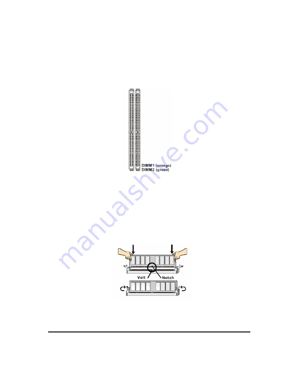
2-4 Install DDRII Memory Module 


The MX945GM-D provides two DIMM slots for 240-pins Dual Channel DDRII 533/667 DIMM, 

which supports the memory size up to 4GB. Since DDRII modules are not interchangeable with 

DDRI and DDRII standard is not backward compatible, only DDRII memory module is allowed to be 

installed in DIMM slots (“DIMM1” and “DIMM2”). Otherwise, the system won’t be able to boot up and 

mainboard might be damaged.  


1. There is one notch on the center of DDRII memory module. The module will only fit 

     in the right orientation. 


2. Insert the DDRII memory module vertically into the DIMM slot. Then push it in until 

    the gold fingers on memory module is deeply inserted in the DIMM slot. 


      3. Make sure the plastic clips on both ends of DIMM slot are locked on the DDRII 

          memory module securely. 


Summary of Contents for MX945GM-D

Page 1: ...MX945GM D User s Manual Revision 1 0 http www bcmcom com...

Page 2: ...he implied warranties or conditions of this product s fitness for any particular purpose In no event shall we be liable for any loss of profits loss of business loss of data interruption of business o...

Page 3: ...aration by the manufacturer or his authorized representatives that the electrical equipment to which it relates satisfies all the provisions of the 1994 Regulations FCC Compliance FCC stands for Feder...

Page 4: ...2 2 7 2 SERIAL ATAII CONECTORS SATA1 SATA2 12 2 7 3 FAN POEWR CONNECTORS SYSFAN1 CPUFAN1 13 2 7 4 FRONT PANEL CONNECTOR JFP1 13 2 7 5 FRONT PANEL AUDIO CONNECTOR JAUD1 14 2 7 6 FRONT USB CONNECTORS F_...

Page 5: ...3 9 PNP PCI CONFIGURATION SETUP 33 3 10 PC HEALTH STATUS 34 3 11 FREQUENCY VOLTAGE CONTROL 35 3 12 LOAD FAIL SAFE OPTIMIZED DEFAULTS 35 3 13 SET SUPERVISOR PASSWORD 36...

Page 6: ...Release Feb 2007 Item Checklist R MX945GM D board R MX945GM D Quick Installation Guide R MX945GM D User s Manual on CD Digital Format R MX945GM D Device Drivers on CD R 80 wire ATA66 100 IDE cable x1...

Page 7: ...RT video output Audio Line Out and 2 COM ports Furthermore the MX945GM D also comes withfour USB2 0 ports on back panel and two internal USB2 0 ports headers This board met today s market demand of lo...

Page 8: ...y Socket Two 240 pin 1 8V DDRII slots Supports DDRII 533 667 SDRAM 4GB max Expansion Slot One 32 bit PCI slot Integrate IDE One IDE port by Intel ICH7 MDH IDE port supports PIO Ultra ATA 66 100 modes...

Page 9: ...MX945GM D 4 1 3 System Diagram MX945GM D Mainboard Diagram...

Page 10: ...PU 3 Install CPU Heatsink It is recommended to add proper amount of thermal compound between the CPU Heatsink and CPU 4 Install System Memory 5 Install Expansion cards If there is any 6 Connect IDE an...

Page 11: ...MX945GM D 6 2 2 The Jumper Connector Location...

Page 12: ...insert the CPU to the CPU socket gently 3 Turn the screw to Lock position NOTE Do not force CPU into the socket It may bend the pins and damage the CPU WARNING Be sure there is sufficient air circulat...

Page 13: ...allowed to be installed in DIMM slots DIMM1 and DIMM2 Otherwise the system won t be able to boot up and mainboard might be damaged 1 There is one notch on the center of DDRII memory module The module...

Page 14: ...itch to 2 pins Power On jumper pole on the motherboard When the power switch on the back of the ATX power supply turned on the full power will not come into the system board until the front panel powe...

Page 15: ...peed digital interconnection between the computer and its display device To connect a LCD monitor simply plug the DVI connector from LCD monitor into the DVI port Refer to the LCD monitor user s manua...

Page 16: ...ectors The audio connectors are used for audio devices Line In blue audio jack Or Side surround Out in 5 1 channel mode Line In is used for external CD player or other audio devices Line Out green aud...

Page 17: ...2 SATA1 SATA2 are dual high speed Serial ATAII interface ports Each supports data transfer rate up to 300MB s These two connectors are fully compliant with Serial ATA specification Each Serial ATA con...

Page 18: ...he black wire is designated for Ground and should be connected to GND pin WARNING Be sure there is sufficient air circulation across the processor s heatsink and Chassis FAN is working correctly Other...

Page 19: ...wise the Line Out connector on the back panel will not function 2 7 6 Front USB Connectors F_USB1 F_USB2 The MX945GM D provides two standard USB 2 0 headers USB 2 0 technology increases data transfer...

Page 20: ...ly from external battery to maintain the system configuration data When it is necessary to clear the system configuration use Clear CMOS jumper CLR_CMOS1 to clear data Follow the instructions below to...

Page 21: ...tors and press it into the PCI slot firmly 3 Set up the BIOS if necessary 4 Install the software driver for installed PCI card that is provided by the PCI card manufacturer 2 8 2 Standard Interrupt As...

Page 22: ...s to the microprocessor The PCI IRQ pins are typically connected to the PCI bus pins as follows IMPORTANT If install PCI card on shared PCI slot make sure that the PCI card driversupports Shared IRQ o...

Page 23: ...eature The system will then run power on test While the test is running the BIOS will alarm beeps or additional message will appear on the screen If user does not see any thing within 30 seconds from...

Page 24: ...in menu the option user wants to confirm or to modify Press F10 when user has completed the setup of BIOS parameters to save these parameters and to exit the BIOS Setup menu Press Page Up Page Down or...

Page 25: ...pset Features Integrated Peripherals Power Management Setup PnP PCI Configurations PC Health Status Frequency Voltage Control Load Fail Safe Defaults Load Optimized Defaults Set Supervisor Password Se...

Page 26: ...the BIOS default values that are factory settings for the stable performance system operation Load Optimized Defaults Use this menu to load the BIOS default values that are settings for optimal perfor...

Page 27: ...one IDE Secondary Master None IDE Secondary Slave None Drive A 1 44M 3 25 in Drive B None Video EGA VGA Halt On All But Keyboard Base Memory 640K Extended Memory 56320K Total Memory 57344K Menu Level...

Page 28: ...pe manually If user selects Manual option related information is asked to be entered to the following items Enter the information directly from the keyboard This information should be provided in the...

Page 29: ...displays every current removable device installed Use PageUp or PageDown key to select the first boot removable device Hard Disk Boot Priority Press ENTER to enter a sub menu which displays every cur...

Page 30: ...Status The default value is On On default Keypad is numeric keys Off Keypad is arrow keys Security Option This category allows user to limit access to the system and Setup or just to Setup System The...

Page 31: ...0 Save ESC Exit F1 General Help F5 Previous Values F6 Optimized Defaults F7 Standard Defaults On Chip Frame Buffer Size Frame Buffer is the video memory that stores data for video display frame This f...

Page 32: ...Standard Defaults OnChip IDE Device Please refer to section 3 7 1 Onboard Device Please refer to section 3 7 2 Super IO Device Please refer to section 3 7 3 Onboard LAN Boot ROM This item allows user...

Page 33: ...lected if user wants to have RAID feature if there are two SATA HDDs On Chip Serial ATA This setting is used to specify the SATA Controller The settings are Disabled Disable the SATA Controller Auto P...

Page 34: ...ntroller This item allows user to enable disable the onboard USB controller USB 2 0 Controller This item allows user to enable disable USB 2 0 function USB Keyboard support This item allows user to en...

Page 35: ...10 Save ESC Exit F1 General Help F5 Previous Values F6 Optimized Defaults F7 Standard Defaults Onboard FDC Controller This item allows user to enable disable onboard floppy disk controller function Av...

Page 36: ...system supports ACPI such as Windows 98SE Windows 2000 and Windows XP the user can choose to enter the Standby mode in S1 POS or S3 STR through the setting of this field The available options are S1 P...

Page 37: ...time at which the RTC real time clock alarm awakens the system from suspend mode PWRON After PWR fail This item specifies whether the system will reboot after a power failure or interrupt occurs Avai...

Page 38: ...Enter Select PU PD Value F10 Save ESC Exit F1 General Help F5 Previous Values F6 Optimized Defaults F7 Standard Defaults Init Display First This setting specifies which VGA device is set as the prima...

Page 39: ...Temperature 35 C 95 F Shutdown Temperature Disable System Fan Speed 0 RPM CPU Fan Speed 0 RPM VCore 1 25 V 12 V 3 331 V 1 5 V 5 24 V 5 V 11 542V 12V 11 12 V 5V 5 09 V VBAT V 3 23 V 5VSB V 5 221 V Men...

Page 40: ...led Spread Spectrum This item allows user to set the CPU Host PCI clock and Spread Spectrum The settings are Enabled Disabled 3 12 Load Fail Safe Optimized Defaults Load Fail Safe Defaults When press...

Page 41: ...ort the selection and not enter a password To disable a password just press Enter when prompted to enter the password A message will confirm that the password will be disabled Once the password is dis...

Reviews: