BBV Tx1000 Installation Manual Download Page 1


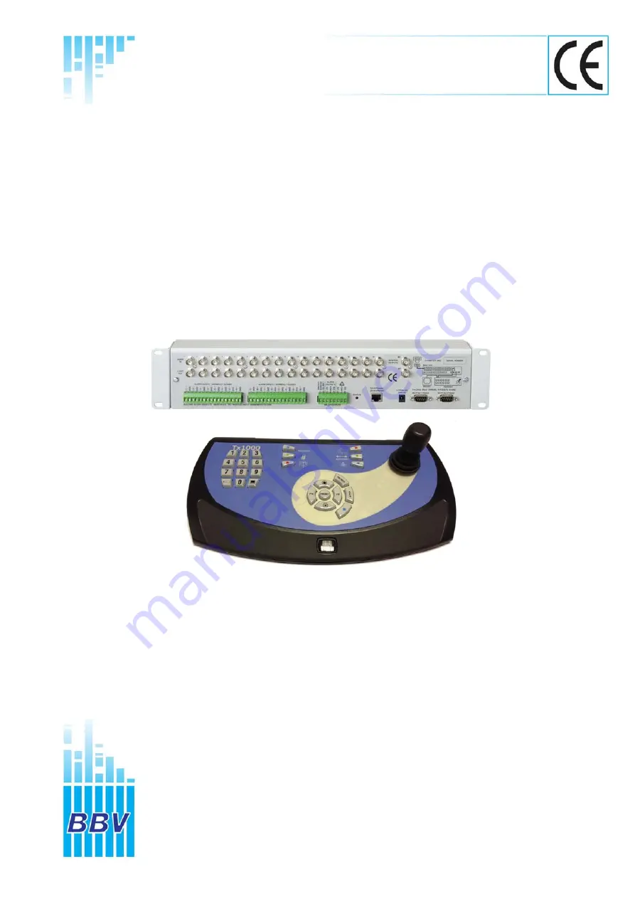
TX1000 Telemetry Transmitter 

Building Block Video Ltd 

17 Apex Park   

Diplocks Industrial Estate 

Hailsham, East Sussex, BN27 3JU, UK 

Tel: + 44 (0) 1323 842727 

Fax: + 44 (0) 1323 842728 

Support: + 44 (0) 1323 444600 

www.bbvcctv.com 

Model Shown: Tx1000/16 


Installation 

Guide


Summary of Contents for Tx1000

Page 1: ...ter Building Block Video Ltd 17 Apex Park Diplocks Industrial Estate Hailsham East Sussex BN27 3JU UK Tel 44 0 1323 842727 Fax 44 0 1323 842728 Support 44 0 1323 444600 www bbvcctv com Model Shown Tx1...

Page 2: ...requirements 9 Priority control between 2 keypad systems 9 Text display on screen 9 Enabling Disabling programming key 10 Camera selection 11 Monitor selection 11 Activating the sequence 11 Programmin...

Page 3: ...he unit is in proper operating condition Coax grounding If an outside cable system is connected to the unit be sure the cable system is grounded Adhere to safety standards All normal safety precaution...

Page 4: ...tter for 8 cameras with 2 monitor outputs 16 alarm input card and joystick Keypad Tx1000 8 MU Telemetry transmitter for 8 cameras with 2 monitor outputs no Keypad Tx1000 8A MU Telemetry transmitter fo...

Page 5: ...or outputs 16 alarm input card and joystick KBD X X X X X X X Tx1000 8 MU Telemetry transmitter for 8 cameras with 2 monitor outputs no KBD X X X X X X Tx1000 8A MU Telemetry transmitter for 8 cameras...

Page 6: ...larm contact over coax Optional TXLD RS422 link Distance 1200m Twin Twisted Pair Rx55X DC P T Zoom Focus Iris 32 Presets with 3 or 4 Aux 8 local alarms 12Vdc plug PSU TX1000 KBD Rx45X AC P T Zoom Focu...

Page 7: ...es 2 keypads supported 2 monitor outputs 8 16 camera inputs Optional alarm input Up the coax RS422 telemetry supported Can be powered off 12V vehicle supply Installation Base unit is 2U 19in rack moun...

Page 8: ...ower supply to the keypad via the 2 1mm power connector 5 Connect either a second video monitor or the second keypad to Output 2 Note that even if both keypads are local to the main unit the second ke...

Page 9: ...und Tx1000 Main Unit DB9 Female Keyboard DB9 Male Keypad power requirements Fully isolated 12Vdc power supply The maximum current draw is 150mA Priority control between two keypad systems Keypad one h...

Page 10: ...y press and hold the focus far and focus near buttons and apply power to the keyboard If the key is blue the programming is enabled If the key is red the programming is disabled If nothing is pressed...

Page 11: ...uence Pressing the sequence key will start the camera sequence on the monitor that is currently selected The on screen display changes from CAM XX to SEQ XX to indicate that the sequence is running To...

Page 12: ...inviting the operator to enter a number from the table above followed by the cam button to set the time delay Menu Option And Delay Number PROGRAM After entering the delay value the screen clears Squ...

Page 13: ...n switches on the Tx1000 keypad These are Iris Open Iris Close Focus Near and Focus Far Zoom In Zoom Out are controlled via the joystick Press and hold or twist until the desired picture is obtained N...

Page 14: ...at receiver then press and then the 2 key followed by the camera button The screen text will clear and Self Test will be activated See the RX Series Telemetry Receiver Installation Handbook for more d...

Page 15: ...programmed preset enter the number of the preset you would like to move to and then press the preset button To programme a preset first position the camera using the Up Down and Left Right arrows The...

Page 16: ...programming function with the BBV Tx1000 keypad Once a preset has been programmed it is automatically included in Patrols 1 and 2 To Remove a Preset from a Patrol 1 Select the receiver on which the p...

Page 17: ...functions Four additional spare functions are provided which are used to carry out advanced programming depending on the type of receiver and or dome used Please refer to the receiver s manual for det...

Page 18: ...cable are used to connect the telemetry connector RB RA GND TRB TRA RB RA GND TRB TRA RB RA GND TRB TRA When daisy chaining the RS422 telemetry ensure that the end of line receiver has RS422 terminat...

Page 19: ...for a programmed length of time The contacts are accessed via contacts 3 4 5 on the smaller green RELAY CONTACTS connector Reset N C Set N O Common 1 2 3 4 5 6 7 8 TIME LAPSE Linking pins 1 2 will dis...

Page 20: ...of time If the sequence is running then the alarm time is added to the sequence time and the sequence continues to run after the alarm times out If the sequence is not running the alarm message and se...

Page 21: ...AL dome interface has 4 local alarm inputs and the Rx45X and Rx55X have 8 local alarm inputs All have a single normally closed relay output that opens momentarily when a local alarm is activated This...

Page 22: ...power is applied you will see the function keys glow pink You can test each individual button by pressing it As a button is pressed it will beep and it will turn white if this happens we know the key...

Page 23: ...PROGRAM 11 INPUT NUMBER CAMERA NUMBER PRESET PROGRAM 11 1 to 16 1 to 8 or 1 to 16 1 to 16 PROGRAM 11 1 PROGRAM 11 2 PROGRAM 11 3 PROGRAM 11 4 PROGRAM 11 5 PROGRAM 11 6 PROGRAM 11 7 PROGRAM 11 8 PROGRA...

Page 24: ...TX1000 Manual V8 September 2013 24 PROGRAM 11 15 PROGRAM 11 16...

Page 25: ...K BN27 3JU If this card is returned with the serial number of the product and the Installation company details BBV will extend the warranty period from 12 Months to 36 Months I do not require any othe...

Reviews: