background image

3   Disassembly / Assembly

3 - 20

Infusomat® compact

plus

 P 1.0  

EN

For internal use, only
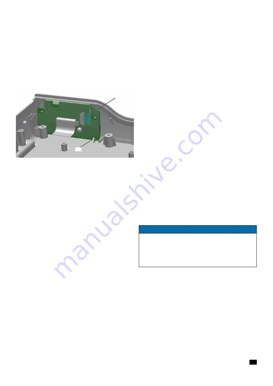
Assembly

1. Guide the ribbon cable through the slot (

Fig. 3 - 25 / Item 1

) in 

the display board.

2. Position the display board upright between the housing wall 

and spigot (

Fig. 3 - 25 / Item 2

).

3. Establish all cable connections.
4. Tighten the screws with a torque of 0.27 Nm ± 0.03 Nm (first 

and second screwing).

3.13 HOUSING, UPPER PART

Designation

Ord. No.

Housing, upper part ICPP . . . . . . . . . . . . . . . . . . . . . . . . .  34522291


with keypad (devices with serial number 1199 and lower)

Housing, upper part ICPP . . . . . . . . . . . . . . . . . . . . . . . . .  34522290


with keypad and display

Fig. 3 - 25
1 Slot for ribbon cable for membrane keyboard
2 Catch for display board

1

2

NOTICE

Starting with serial number 1200 of the device, the display board 
with display is affixed to the housing, upper part with keypad. If 
one of these components is defective, the housing upper part 
including keypad and display board with display has to be 
replaced with the corresponding spare part, ord. no 34522290.

Summary of Contents for 8717070

Page 1: ...Infusomat compactplus P Service Manual EN Version 1 0 For internal use only For internal use only...

Page 2: ...le in the following languages from the B Braun Service Portal Designation Doc No Infusomat compactplus P I0003_000615 Service Manual German OTHER APPLICABLE DOCUMENTS This Service Manual is valid only...

Page 3: ...15 Safety officer 30 MPG 0 15 Service portal 1 1 Overview of the Device 1 1 System overview 1 2 Description of device 1 2 Intended use 1 2 Device overview 1 2 Mechanical design 1 3 Function 1 5 Unit...

Page 4: ...epair 5 1 Servicing the Unit 5 1 Cleaning and disinfecting 5 1 Servicing the battery 6 1 Technical Safety Check TSC 6 1 Checklist for Technical Safety Check TSC 7 1 Procedural Instructions on the TSC...

Page 5: ...n which a TSC is mandatory B Braun pre scribes an interval of 24 months The owner may decide on shorter intervals or shorter intervals may be prescribed by the law The TSC obligation applies independe...

Page 6: ...ng enhancements new settings changes or repairs are carried out by duly authorized persons the electrical installation in the corresponding room meets the requirements of the IEC 60364 7 710 and appli...

Page 7: ...on Each workstation must be equipped according to the recommen dations with the necessary static protective measures if ESD com ponents or boards are handled Fig 0 1 Each workstation must be equipped...

Page 8: ...rsonnel are responsible for assuring regular or additional recalibration of their test equipment at any time Original test equipment must be calibrated at the works of B Braun Further information is a...

Page 9: ...nder de com en or comparable Voltage measurement For example Multimeter Fluke 177 fluke com en us or comparable Clearance measurement Slip gauges According to DIN 2275 tolerance T2 or better For examp...

Page 10: ...mybbraun Service Portal SETTING OFF Warnings and notes Additional notes and warnings are set off as follows References References to chapters are shown as follows see Setting off p 0 10 References to...

Page 11: ...enu commands are described as Menu File SPECIAL PDF FUNCTIONS In the PDF format of this manual special functionality is inte grated which can be used with Adobe Reader Form function For completing sav...

Page 12: ...erally known but are used in this Service Manual are listed below CE Communaut Europ enne European Community CP compactplus System DIN Deutsche Industrie Norm German Industrial Standard EN Europ ische...

Page 13: ...Technology Inc Commodore Semiconductor Group PCP Perfusor compactplus STCP Station compactplus rack system TEMP Temperature TSC Technical Safety Checks VDE Verband der Elektrotechnik Elektronik und I...

Page 14: ...Important Preliminary Remarks 0 14 Infusomat compactplus P1 0 EN For internal use only For your notes...

Page 15: ...chnicians Intercompany e mail Spare Parts_HC bbraun com SERVICE HOTLINE Service hotline international e Mail Service Hotline_HC bbraun com RETURNS Return of spare parts test equipment and units for ca...

Page 16: ...Contact Information 0 16 Infusomat compactplus P1 0 EN For internal use only For your notes...

Page 17: ...drip stand using the pole clamp The Station compactplus allows the set up of a complete pump system with up to 18 pumps Up to three pumps can be installed in every Station compactplus The pumps are s...

Page 18: ...part and the upper part The pump door is screwed to the housing bottom part The pole clamp is mounted on the rear of the housing The operating unit keyboard and display is integrated into the front of...

Page 19: ...onitors the battery cells and controls their charge condition Processors The function processor controls all the functions of the Infusomat compactplus P Data is stored in a non volatile memory Extern...

Page 20: ...nnector Accessories X8 Connector Keypad Display X1 Connector Sensors Actuators Interface not in use Keypad Integrated in Housing upper part PCB Sensors Housing lower part Power Supply Inlet Connector...

Page 21: ...via the USB service adapter CP see compactplus Service Tool Instructions for Use Fig 1 4 Software version information Position 1 2 3 4 5 6 7 8 9 10 Digit I 0 0 0 3 A 0 0 0 1 Version Deployment versio...

Page 22: ...114 Power cord ZA IN 8717115 Power cord CN 8717117 Power cord DK 8717118 Power cord BR 8717119 Power cord AR 8717121 All cables have a length of 2 5 m it is necessary to use one of the power cords lis...

Page 23: ...1 6 Seal is present and undamaged 1 7 Infusomat compactplus P is clean 3 5 Administer a bolus by preselecting a volume of 3 ml bolus is administered volume counter counts up 2 Switching on and Self te...

Page 24: ...1 Overview of the Device 1 8 Infusomat compactplus P1 0 EN For internal use only For your notes...

Page 25: ...d An audible signal is output the red LED flashes and a staff call is triggered The message Alarm and the cause of the alarm appear on the display Device alarm If a device alarm is output infusion is...

Page 26: ...using 326 Key panel not confirmed by KuP Hardware defect Change upper part of housing 350 Pressure values delayed Software failure 358 Unexpected error in the timer management of the pump Software fai...

Page 27: ...rror codes respectively For example FuP 110 error code 10 CPU self check failure KuP 500 error code 56 error on program flow 750 Key panel key activated Key panel faulty Change upper part of housing 7...

Page 28: ...eaker 19 Grafic processor monitoring failure If error appears frequently Hardware defect 20 Common Time Base monitoring failure If error appears frequently Hardware defect Change main PCB 21 Key panel...

Page 29: ...g file 49 Communication failure FuP KuP Software failure If error appears frequently Hardware defect Change main PCB 50 Queue Overflow communication FuP KuP Software failure 51 63 Flow monitoring fail...

Page 30: ...1 Air sensor hardware version invalid 213 Air sensor in service mode Software failure If persisting hardware defect 214 Pressure sensor values out of range Hardware defect 215 Sensor PCB hardware vers...

Page 31: ...ressure by rotating clockwise Fig 2 1 Item 3 If the pressure is too low increase the pressure by rotating counterclockwise Fig 2 1 Item 2 2 Repeat the mechanical pressure test after adjustment 3 If th...

Page 32: ...2 Unit Diagnosis Adjustments 2 8 Infusomat compactplus P1 0 EN For internal use only For your notes...

Page 33: ...n cable must be unlocked completely 1 Carefully push the locks of the connector Fig 3 1 Item 1 on the right and left toward the ribbon cable using a small screwdriver or special tool 2 Pull the ribbon...

Page 34: ...40 Pcs Cover cap housing 100 Pcs Cover cap drive head 5 Pcs Foot 10 Pcs Magnet 7x7x3 5 Pcs Hexagon nut M8 5x1 DIN 934 2 Pcs Speaker flap Lock screw 5 Pcs O Ring 12x3 NBR 50 Shore 5 Pcs Seal ring 3x1...

Page 35: ...only Special screws The special screws for plastic housings are not self cutting but form a thread in the plastic of the housing by deformation when first inserted When inserted subsequently the screw...

Page 36: ...four housing feet Fig 3 2 Item 1 out of the lower part of the housing Assembly 1 Push the housing feet into the guides in the lower part of the housing NOTICE Make sure that the ribbon cable is cente...

Page 37: ...3 1 Disassembly 1 Unscrew the four screws Fig 3 3 Item 1 using a 10IP TORX plus screwdriver 2 Remove the gasket Fig 3 3 Item 2 Assembly Power supply is installed in the housing bottom part 1 Attach t...

Page 38: ...efully lever out the membrane Fig 3 4 Item 1 Assembly Housing front has been mounted to the housing bottom part 1 Check the membrane for damage before mounting to the pump and replace it if necessary...

Page 39: ...tem 2 using a T20 TORX screwdriver 3 Remove the pole clamp Fig 3 5 Item 3 and the sealing Fig 3 5 Item 4 Assembly Battery has been inserted and connected 1 Before inserting the sealing apply high vacu...

Page 40: ...ve the battery Fig 3 8 Item 1 2 Pull off the 3 pole battery cable from the processor board Fig 3 7 4 1 2 3 NOTICE Use new screws whenever the pole clamp has been removed Remove residues from old preco...

Page 41: ...attery route the cable inside the housing toward the processor board and place the battery with the cable facing inwards NOTICE There are two versions of batteries in the market one version with white...

Page 42: ...mlet and remove it 2 Remove the screw Fig 3 10 Item 2 using a 10IP TORX plus screwdriver 3 Slightly lift the second clamp Fig 3 10 Item 3 toward the top and remove it to the side Assembly Unit is clos...

Page 43: ...TORX plus screwdriver 2 Lift the hinges Fig 3 11 Item 2 from the housing bottom part Fig 3 11 Item 4 3 Remove the pump door Fig 3 11 Item 1 Assembly Unit is closed Second clamp has been mounted 1 Tigh...

Page 44: ...ump door has been removed 1 Unscrew the three screws Fig 3 12 Item 1 at the housing front using a 10IP TORX plus screwdriver 2 Pierce the seven cover caps Fig 3 13 Item 2 at the housing bottom part wi...

Page 45: ...ly Fig 3 15 Item 2 on the processor board 8 Disconnect the connector of the stepper motor Fig 3 15 Item 3 on the processor board 9 Completely unlock the connector for the connecting cable of the senso...

Page 46: ...d pressure sensors 1 Place the upper and the lower part of the unit side by side see Fig 3 14 2 Reconnect all plug connections 3 Insert the fixing plate Fig 3 14 Item 3 4 Carefully place the upper par...

Page 47: ...AKER Designation Ord No Loudspeaker CP 34522001 Disassembly Unit has been opened 1 Disconnect the connector of the loudspeaker Fig 3 18 Item 1 on the processor board 2 Completely unlock the speaker br...

Page 48: ...sure that the ridges of the gasket are vertical Fig 3 20 Item 1 4 Route the cable of the loudspeaker through the left opening Fig 3 20 Item 2 of the loudspeaker bracket and connect it to the processor...

Page 49: ...r and remove the processor board Fig 3 21 Item 4 Assembly Accessory connector is mounted 1 Establish all cable connections 2 Tighten the screws with a torque of 0 7 Nm 0 07 Nm first and second screwin...

Page 50: ...ch accessory connector CP 2 Remove the accessory connector Fig 3 22 Item 2 from the rear wall of the unit Assembly 1 Observe the alignment aids when mounting the connector see Fig 3 23 2 Fasten the he...

Page 51: ...s Fig 3 24 Item 4 using an 8IP TORX plus screwdriver and remove the display board Fig 3 24 Item 3 with the display 4 To replace the connecting cable for the display board Fig 3 24 Item 2 completely un...

Page 52: ...USING UPPER PART Designation Ord No Housing upper part ICPP 34522291 with keypad devices with serial number 1199 and lower Housing upper part ICPP 34522290 with keypad and display Fig 3 25 1 Slot for...

Page 53: ...r see Loudspeaker p 3 15 b Accessory connector see Accessory connector p 3 18 c Processor board see Processor board p 3 17 d Display board with display possible for devices with serial number 1199 or...

Page 54: ...r ICP 34774508 Ribbon cable air sensor ICP 34774509 ESD wire ICP 34774510 Membrane see Membrane p 3 6 Magnet see Sets of small parts p 3 1 Disassembly Unit has been opened 1 Remove the cable tie Fig 3...

Page 55: ...rnal use only 3 Remove five screws Fig 3 29 Item 1 using a 15IP TORX plus screwdriver 4 Remove the housing front Fig 3 30 Item 1 from the housing bottom part Fig 3 30 Item 2 Fig 3 29 1 Screw DELTA PT...

Page 56: ...nsor Fig 3 32 Item 2 approx half the way towards the interior of the unit until it is released from the bracket Fig 3 32 Item 3 8 Remove two screws Fig 3 32 Item 4 using a 15IP TORX plus screwdriver 9...

Page 57: ...If the ESD wire has to be exchanged remove the lug terminal from the screw Fig 3 33 Item 3 13 Compress the spring of the pump see arrows and remove the pump Fig 3 34 Item 1 from the housing front Fig...

Page 58: ...nsor downstream Fig 3 35 Item 3 18 Unscrew one screw Fig 3 36 Item 1 using a 10IP TORX plus screwdriver 19 Remove the SHK PCB ICPP Fig 3 36 Item 2 from the SHK unit Fig 3 36 Item 3 Fig 3 35 1 Screw DE...

Page 59: ...re sensors with a torque of 0 25 Nm 0 03 Nm first and second screwing 4 Check the O ring Fig 3 38 Item 2 for damage and replace it if necessary the O ring is contained in the Service part kit 5 Insert...

Page 60: ...6 Nm first and second screwing 10 Push the Hall sensor into the bracket Fig 3 32 Item 3 11 Establish all cable connections to the sensor board 12 Before inserting the housing front apply high vacuum g...

Page 61: ...stepper motor through the cable router see arrows in Fig 3 41 16 Route the ESD wire Fig 3 41 Item 1 through the cable router 17 Fix the cables to the screw boss with a cable tie Fig 3 41 Item 3 18 En...

Page 62: ...tepper motor Fig 3 42 Item 2 3 Unscrew one screw Fig 3 43 Item 1 4 Remove the encoder board Fig 3 43 Item 2 using a 10IP TORX plus screwdriver Assembly 1 Tighten the screw of the encoder board with a...

Page 63: ...been removed see Gasket for rubber connector p 3 5 Unit has been opened 1 Unscrew the two screws Fig 3 44 Item 1 using a 10IP TORX plus screwdriver 2 Remove the power supply Fig 3 44 Item 2 3 If the h...

Page 64: ...ck screw Fig 3 45 Item 1 of the old housing to the new housing from below or use a new lock screw from the Small parts ICP 2 Tighten the screws of the power supply unit with a torque of 0 85 Nm 0 1 Nm...

Page 65: ...ure cut off electronic T6 Pressure limitation mechanical T7 SHK T8 Second clamp T9 Delivery accuracy T10 Air sensor T11 Temperature sensor T12 Staff call test 3 1 Housing foot X X 3 2 Gasket for rubbe...

Page 66: ...door yet 2 Use the Menu button and the arrow keys to select the Settings menu item and confirm with OK 3 Select Service and confirm the device code with OK 4 Confirm selection of All Disposables Off w...

Page 67: ...RUN IN and confirm with OK Fig 4 3 Line calibration is started Fig 4 3 NOTICE This service function is automatically deactivated again after 5 minutes The RUN IN has to be selected within these 5 minu...

Page 68: ...e and readability of the labels Check the unit and the accessories for compatibility Mains power supply cable YES N A T2 Electrical Safety Protective conductor resistance of mains connecting line 0 1...

Page 69: ...xing the Seal Pump is sealed with a new seal Mech Aids and Measuring Equip Used Accessories used Disposables Type ________________________ Part No _____________________ Manometer Ident No ____________...

Page 70: ...nt is undamaged h Pressure sensor upstream i Second clamp j Keypad display Keypad display is clean and undamaged correct bonding of the foil k Accessory connector Accessory connector is clean and unda...

Page 71: ...ns correctly 2 Fit the unit to be tested underneath another compactplus device and check that the lock functions correctly 3 Rotate the pole clamp in all directions 4x90 and check for correct latching...

Page 72: ...t off and disconnect from mains power supply b Switch the unit on Self test is performed c Insert a line and let the pump run d Connect disconnect and reconnect the unit to from mains power supply wai...

Page 73: ...ubble injection 1 piece Electronic pressure gauge with peak value recognition 1 piece Graduated cylinder 25 ml 0 04 ml 1 piece T5 Pressure cut off electronic 1 Insert the Intrafix Primeline of the tes...

Page 74: ...mpare with the specifications in the checklist 8 Check all pressure stages listed in the checklist and document values Do not reduce pressure T6 Pressure limitation mechanical Pmax 1 Deactivate electr...

Page 75: ...the SHK Fig 4 6 left 3 Move the pump door towards the closed position as far as possible keeping the door opener in closed position The second clamp opens see Fig 4 7 right 4 Read off the PSHK value o...

Page 76: ...Measurement 1 Set a volume of 30 ml VTBI to reduce possible spilling 2 Insert the Intrafix Primeline of the test setup Fig 4 2 in the device Do not stretch the line when inserting 3 Close three way c...

Page 77: ...he pump 3 Hang the outlet cannula over the measuring container and at the same time start the stop watch and the Infusomat compactplus P 4 After the time has expired stop the stop watch and the Infuso...

Page 78: ...play the air sensor information see T10 Air sensor p 4 13 2 Read off the values of the FuP and KuP temperature sensors on the LC display and compare the difference with the specifications in the check...

Page 79: ...Instructions fo Use for a detailed description on how to clean and disinfect the Infusomat compactplus P Heed to the disposal and hygienic instructions Accessories Clean the accessories according to...

Page 80: ...5 Servicing the Unit 5 2 Infusomat compactplus P1 0 EN For internal use only For your notes...

Page 81: ...essure sensor downstream membrane Pump membrane Pressure sensor upstream mem brane Second clamp Keypad display Accessory connector IR window Mains power supply connection Accessories Cleanliness compl...

Page 82: ...stage 9 0 7 1 3 bar _____ bar or 10 19 psi _____ psi Pressure limitation mechanical Delivery rate 250 ml h Pmax 2 4 4 0 bar _____ bar or 35 58 psi _____ psi SHK Is closed after opening the pump door...

Page 83: ...il ________________ Measuring Adapter Accessory Connector CP Graduated cylinder Stop watch ___________________________ ___________________________ Mains power supply cable Staff call cable compactplus...

Page 84: ...6 Technical Safety Check TSC 6 4 Infusomat compactplus P1 0 EN For internal use only For your notes...

Page 85: ...front is undamaged h Pressure sensor upstream i Second clamp j Keypad display Keypad display is clean and undamaged correct bonding of the foil k Accessory connector Accessory connector is clean and...

Page 86: ...ock functions correctly 2 Fit the unit to be tested underneath another compactplus device and check that the lock functions correctly 3 Rotate the pole clamp in all directions 4x90 and check for corre...

Page 87: ...the unit off and disconnect from mains power supply b Switch the unit on Self test is performed c Insert a line and let the pump run d Connect disconnect and reconnect the unit to from mains power su...

Page 88: ...ction 1 piece Electronic pressure gauge with peak value recognition 1 piece Graduated cylinder 25 ml 0 04 ml 1 piece Pressure cut off electronic 1 Insert the Intrafix Primeline of the test setup Fig 7...

Page 89: ...eduction and compare with the specifications in the TSC 8 Check all pressure stages listed in the TSC and document values Do not reduce pressure Pressure limitation mechanical Pmax 1 Deactivate electr...

Page 90: ...ng of the SHK Fig 7 6 left 3 Move the pump door towards the closed position as far as possible keeping the door opener in closed position The second clamp opens see Fig 7 7 right 4 Read off the PSHK v...

Page 91: ...5 ml Measurement 1 Set a volume of 30 ml VTBI to reduce possible spilling 2 Insert the Intrafix Primeline of the test setup Fig 7 2 in the device Do not stretch the line when inserting 3 Close three w...

Page 92: ...n stop the pump 3 Hang the outlet cannula over the measuring container and at the same time start the stop watch and the Infusomat compactplus P 4 After the time has expired stop the stop watch and th...

Page 93: ...here is no longer any water in the line 9 Display sensor information via Sensor info menu item 10 Wait at least 120 seconds 11 Read off the Air Voltage value and document Temperature sensor 1 Display...

Page 94: ...7 Procedural Instructions on the TSC 7 10 Infusomat compactplus P1 0 EN For internal use only For your notes...

Page 95: ...call cable compactplus 8718030 Intrafix Primeline Standard PVC 240 cm 8700310 Injection port c2454540 Measuring Adapter Accessory Connector CP 7705208 Graduated cylinder Manometer Syringe 10 ml Syring...

Page 96: ...nnector CP For ordering the torque screwdriver set and for further queries please exclusively contact WERMAS Werkzeughandels GmbH Justus Liebig Str 1 34253 Lohfelden Germany Tel 49 5615 7069 0 Fax 49...

Page 97: ...plate 3 Pcs Sealing pole clamp 3 Pcs IR LED 100 mA OSRAM IRL 81 A 2 Pcs Hall sensor A3212EUA T 2 Pcs Optical sensor TSL254R 2 Pcs Halkey Robt Swabable T port PC 245454024 2 Pcs Designation Order No BN...

Page 98: ...9 Spare Parts List 9 2 Infusomat compactplus P1 0 EN For internal use only Fig 9 1 Exploded drawing Infusomat compactplus P 2 1 3 5 4 7 21 19 10 9 8 12 11 20 17 15 13 14 6 16 18...

Page 99: ...stepper motor and encoder PCB 7 Stepper motor CP 34522107 8 Encoder PCB ICP 34522205 SN 9 Pole Clamp complete CP 34522004 BN 10 Gasket for rubber connector CP 34522010 BN 11 Power supply CP 34522000...

Page 100: ...9 Spare Parts List 9 4 Infusomat compactplus P1 0 EN For internal use only For your notes...

Page 101: ...al inspection 7 2 Operational test 7 2 Functional test 1 7 L List of abbreviations 0 12 Log files 2 1 Loudspeaker 3 15 M Mechanical design 1 2 O Options 1 6 Overview Device 1 2 System 1 1 P Product sa...

Page 102: ...use only T Technical data 1 6 Technical Safety Check 0 5 6 1 Test equipment 8 1 Tools 8 1 TSC 0 5 6 1 U Unit Accessories 1 6 Opening closing 3 12 Options 1 6 Software 1 5 Technical data 1 6 V Visual...

Page 103: ...al CURRENT INFORMATION n a HISTORY OF SPARE PARTS Changed or updated spare parts Designation Ord No Modification Starting with SN of unit module Housig upper part ICPP 34522290 Spare part includes dis...

Page 104: ...er Working hours Customer nr Inventory nr Cust ref nr Software version Problem description Work performed Labor details Activity Type Work Note Quantity Unit Parts consumed Article number Name Serial...

Page 105: ......

Page 106: ...B Braun Melsungen AG Carl Braun Stra e 1 34209 Melsungen Germany Phone 49 5661 71 0 Fax 49 5661 71 4567 www bbraun com Doc No I0003_000616 Version 1 0 For internal use only...

Reviews: