hydroheat.com.au
20
910.026.1 - EN (AUS)
ISTRUCTIONS PERTAINING TO THE INSTALLER
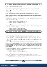
The pumps of the heating system (P1 and P2) have to be connected to boiler terminal block following the wir-
ing of gure 9, a relay must be wired between the boiler control circuit board and the pumps.
12.2 CONNECTING THE PUMPS
Figure 9
Terminal board
Terminal board
Terminal board
Cover
Cover
0902_1202 / CT_0676
Turn the control box downward to access terminal blocks M1 and M2 used for the electrical connections by
removing the two protective covers (see gure 8).
Terminals 1-2
: connections for the optional SIEMENS QAA73 temperature regulator. These connections do
not have any speci c polarity.
Remove the bridge between terminals 1-2 “TA” on terminal
block
M1.
Read the instructions provided with the temperature regulator to ensure correct installation and programming.
Terminals 3-4
: room temperature thermostat “TA”. Thermostats with integral accelerator resistor must not be
used. Check that there is no voltage across the ends of the two thermostat connection wires.
Terminals 5-6
: oor temperature thermostat connection “TP” (commercially available device). Check that
there is no voltage across the ends of the two thermostat connection wires.
Terminals 7-8
: connections for the optional SIEMENS QAC34 outdoor temperature sensor. Read the instruc-
tions provided with the outdoor temperature sensor to ensure correct installation.
Terminals 9-10
: connections for the optional domestic hot water priority sensor, for connecting single system
boilers to external DHW boilers.
Terminals a-b (230V AC; 50 Hz; 0,5 A max; cos
ϕ
> 0,8)
: electricity supply for boiler pump.
(Feeding relay coil).
12.3 DESCRIPTION OF THE ELECTRICAL CONNECTIONS TO THE BOILER


