


The system must be cleaned with Fernox F3
Power flush the system according to the power flush equipment supplier's instructions.
Fernox MB1 inhibitor must be added according to the supplier's instructions.
Following the treatment process a sample of system water must be taken and sent to Fernox for analysis to confirm the system cleaning and dosing process has been
successful. A copy of the report to be sent to Baxi Heating UK Ltd, heateam, Ecogen team, Brooks House, Coventry Road Warwick CV3 4LL.
3. Please be aware of the resistance chart for this appliance, and if you are replacing a low resistance boiler ie. old cast iron, the system will need to be rebalanced (See
).
4. The following conditions should be observed on all systems:
Drain cocks should be fitted to all system low points.
All gas and water pipes and electrical wiring must be installed in a way which would not restrict the servicing of the boiler.
Position isolating valves as close to circulating pump as possible.
6.2 Treatment of Water Circulating Systems
1. All recirculatory water systems will be subject to corrosion unless they are flushed and an appropriate water treatment is applied. To prevent this, follow the guidelines
given in BS 7593 "Treatment of Water in Domestic Hot Water Central Heating Systems" and the treatment manufacturers instructions.
2. Treatment must involve the use of a proprietary cleanser, such as Fernox F3 and an inhibitor such as Fernox MB1.
3. Full instructions are supplied with the products, for further information contact Fernox (0870 870 0362).
Failure to flush and add inhibitor to the system will invalidate the appliance warranty.
4. It is important to check the inhibitor concentration after installation, system modification and at every service in accordance with the inhibitor manufacturer's instructions.
(Test kits are available from inhibitor stockists.)
5. For information or advice regarding any of the above contact Technical Enquiries 0844 871 1555.
page 12
6.3 Pipework
1. The sizes of flow and return pipes from the boiler should be determined by normal methods, according to the requirements of the system. The connections to the boiler will
accept 22mm pipe fittings. Compression fittings must be used to prevent heat damage to the boiler (as supplied see
).
2. A 20 °C drop in temperature across the system is recommended for condensing boilers, but where radiator sizing is marginal it may be advisable to retain a system
temperature drop of 11°C.
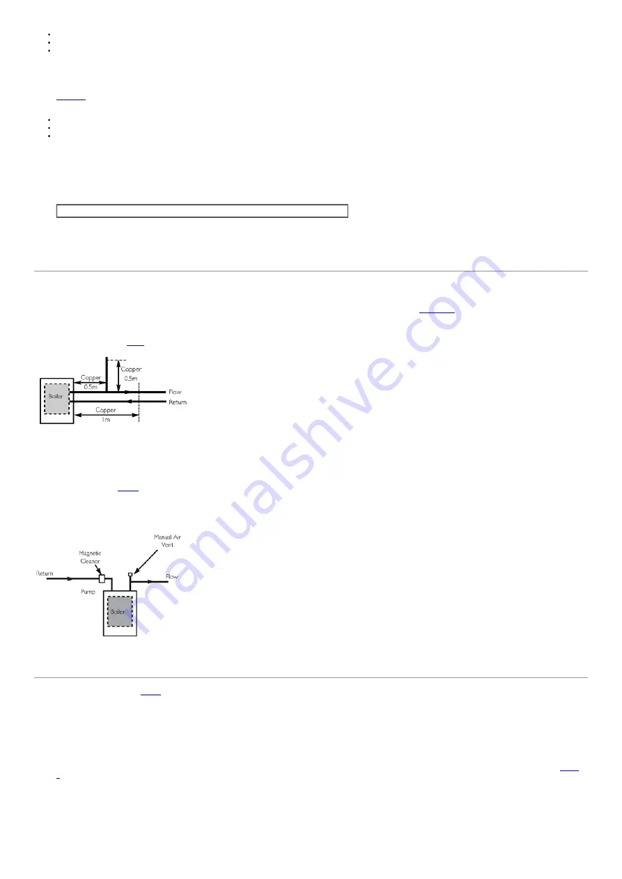
3. In systems using nonmetallic pipework it is necessary to use copper pipe for the boiler Flow and Return. The copper must extend at least 1 metre from the boiler and
include any branches (
).
Fig. 4
6.4 Bypass Requirements
1. An Automatic Bypass must be fitted. The appliance requires a minimum bypass of 7 l/min for open vented systems.
6.5 Magnetic Cleaner (
)
1. A 'ADEY MagnaClean TwinTech' Magnetic Filter must be fitted on the return to boiler as close to the appliance as possible.
FAILURE TO FIT THIS DEVICE WILL INVALIDATE THE APPLIANCE WARRANTY.
Fig. 5
page 13
6.6 Sealed Systems Details (
1. SAFETY VALVE A safety valve complying with the requirements of BS 6750 Part 1 must be fitted close to the boiler on the flow pipe by means of a horizontal or
vertically upward connection with no intervening valve or restrictions and should be positioned to facilitate testing. The valve should be preset and nonadjustable to
operate at a pressure of 3 bar (45 Ibf/in
2
). It must be arranged to discharge any water or steam through a pipe to a safe outlet position.
2. PRESSURE GAUGE A pressure gauge of minimum range 04 bar (060 Ibf/in
2
) with a fill pressure indicator must be fitted to the system, preferably at the same point as
the expansion vessel in an easily visible position.
3. EXPANSION VESSEL An expansion vessel complying with the requirements of BS 4814 must be fitted to the system by means of a connection close to the inlet side
of the circulating pump in accordance with the manufacturers instructions, the connecting pipe being unrestricted and not less than 15mm (1/2 in) nominal size. The
volume of the vessel should be suitable for the system water content and the nitrogen or air charge pressure should not be less than the system static head (See
Systems'.
4. FILLING LOOP A filling loop connection on the central heating return pipework must be provided to facilitate initial filling and pressurising and also any subsequent water
loss replacement / refilling. The sealed primary circuits may be filled or replenished by means of a temporary connection between the primary circuit and a supply pipe
provided a 'Listed' double check valve or some other no less effective backflow prevention device is permanently connected at the inlet to the circuit and the temporary
connection is removed after use. The filling method adopted must be in accordance with all relevant water supply regulations and use approved equipment. Your attention
is drawn to, for GB: Guidance G24.2 and recommendation R24.2 of the Water Regulations Guide. for IE: the current edition of I.S. 813 "Domestic Gas Installations".
5. VENTING A method of venting the system during filling and commissioning must be provided by fitting manual vents. Care must be taken to ensure any air in the
system is completely vented.
Summary of Contents for ECOGEN 24/1.0
Page 69: ...Fig 77 Fig 78 Fig 79 page 69 16 0 Schematic Wiring 16 1 Burner Control Units BCU Connections...
Page 70: ...page 70 16 2 Milligrid 24 way Connector...
Page 71: ...page 71 16 3 14 way Connector...
Page 72: ...page 72 16 4 Engine Circuit...
Page 73: ...page 73 16 5 Power Monitoring 24Vdc Power Supply...
Page 74: ...page 74 16 6 External Connections External Wiring...
Page 85: ...page 87...
Page 86: ...page 88...
Page 87: ...page 89 Section P...
Page 88: ...page 90...
Page 89: ...page 91 Section Q Engine developing less than 950W after 15 minutes running at maximum rate...
Page 91: ...page 93 page 94 page 95 page 96 MICRO CHP SYSTEM COMMISSIONING CHECKLIST...
Page 92: ...page 97...


