7.0 Changing Components
14
7.4
Burner
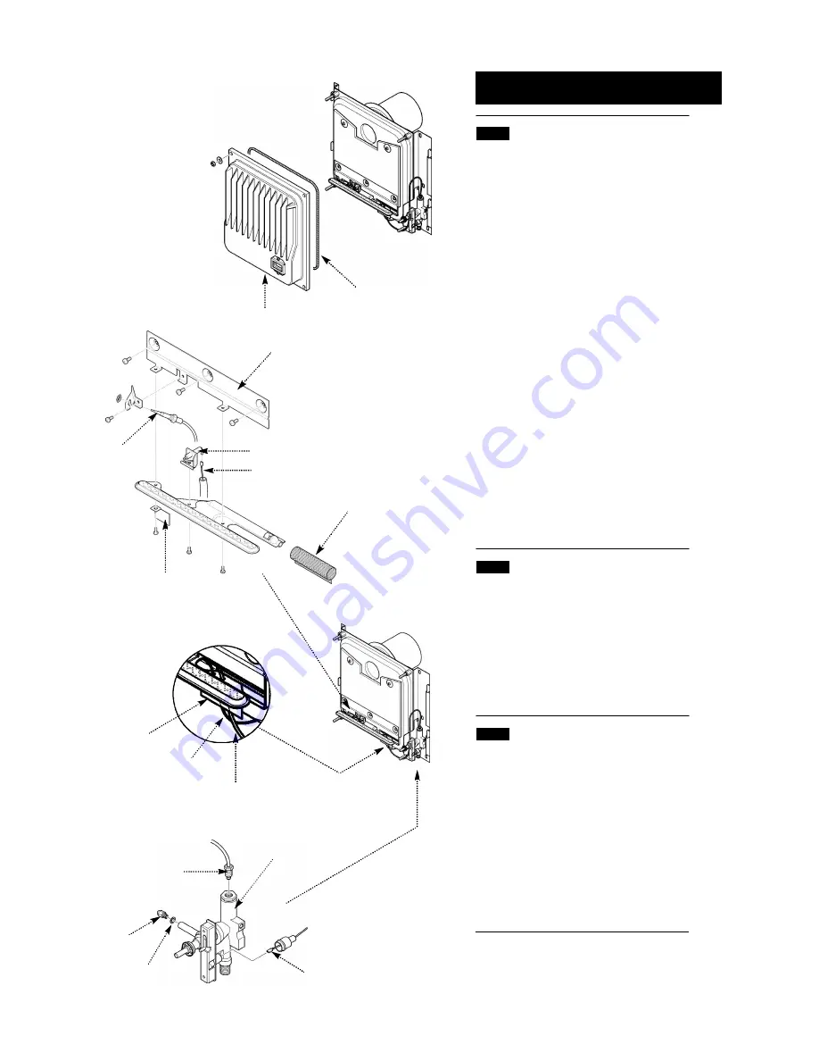
1. Undo the heat exchanger retaining nuts and
washers and draw the casting forwards off the
locating studs (Fig. 25).
2. Remove the three screws holding the burner
retaining plate to the airbox, also remove the
insulation and undo the thermocouple nut from
the gas tap (Fig. 26 & 28).
3. Ease the thermocouple and electrode lead
from the rubber grommet (Fig. 27).
4. Disengage the burner from the injector and
pull the electrode lead off the spark electrode
(Fig. 26).
5. Remove the intake gauze from the burner inlet
and undo the screws securing the burner to its’
retaining plate, noting the position of the shield at
the left hand side (Fig. 26).
6. Undo the screw securing the spark electrode
to the burner. Fit the electrode to the new burner
(Fig. 26).
7. Fit the intake gauze to the burner inlet
ensuring that it covers the primary aeration hole
(Fig. 26).
8. Reassemble in reverse order of dismantling.
7.5
Injector
1. Remove the burner as described in sections
7.4.1 to 7.4.4 .
2. Undo the injector and sealing washer,
retaining the washer for use with the new
injector. If the washer is damaged it must be
replaced.(Fig. 28).
3. Reassemble in reverse order of dismantling.
7.6
Thermocouple
1. Remove the burner as described in sections
7.4.1 to 7.4.4 .
2. Undo the nut retaining the thermocouple tip to
the burner bracket and withdraw the
thermocouple (Fig. 26).
3. Bend the new thermocouple in a similar
manner to the one removed. Avoid any sharp
bends.
4. On reassembly ensure that the airbox sealing
grommet is correctly positioned.
Burner Retaining Plate
Injector
Thermocouple
Gas Tap
Electrode Lead
Washer
Grommet
Electrode Lead
Thermocouple
Spark Electrode
Burner Gauze
Shield
Thermocouple
Electrode Lead
Heat Exchanger Casting
Rope Seal
Fig. 25
Fig. 26
Fig. 27
Fig. 28
© Baxi Heating U.K. Limited 2007.


