Installation
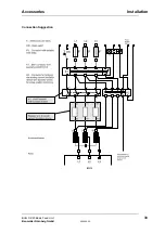
Connection Diagram
24
BUG 3/2/20 Basic Feed Unit
5.96064.02
Baumüller Nürnberg GmbH
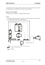
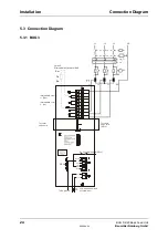
5.3 Connection Diagram
5.3.1 BUG 3
2
230-V additional feed
potential-free!
To further
servo units
(SELV)
Intermediate circuit
L-
Intermediate circuit
L+ (ZK+)
Option E
External ballast resistor or BUR
L1
T1
I>
L1
L2
L3
PE
I>
I>
L2
L3
R2
K2
K1
F1
PE
To further
servo units
To NC ground
1
8
7
6
5
4
3
2
1
K1 Controller enable (SELV)
T2
R
B
(ZK-)
Ready
230 V
pot.-free
Ba+
Ba-
SELV
Reset
M
+15 V
-15 V
+24 V
Summary of Contents for BUG 2
Page 8: ...Abbreviations IV BUG 3 2 20 Basic Feed Unit 5 96064 02 Baumüller Nürnberg GmbH ...
Page 12: ...Safety Information 4 BUG 3 2 20 Basic Feed Unit 5 96064 02 Baumüller Nürnberg GmbH ...
Page 20: ...Transport Unpacking 12 BUG 3 2 20 Basic Feed Unit 5 96064 02 Baumüller Nürnberg GmbH ...
Page 48: ...Installation Accessories 40 BUG 3 2 20 Basic Feed Unit 5 96064 02 Baumüller Nürnberg GmbH ...

