background image

MB154.2

  pog90-esl_mb (09A1) 


18


Elektrischer Anschluss

 / Electrical connection 

6

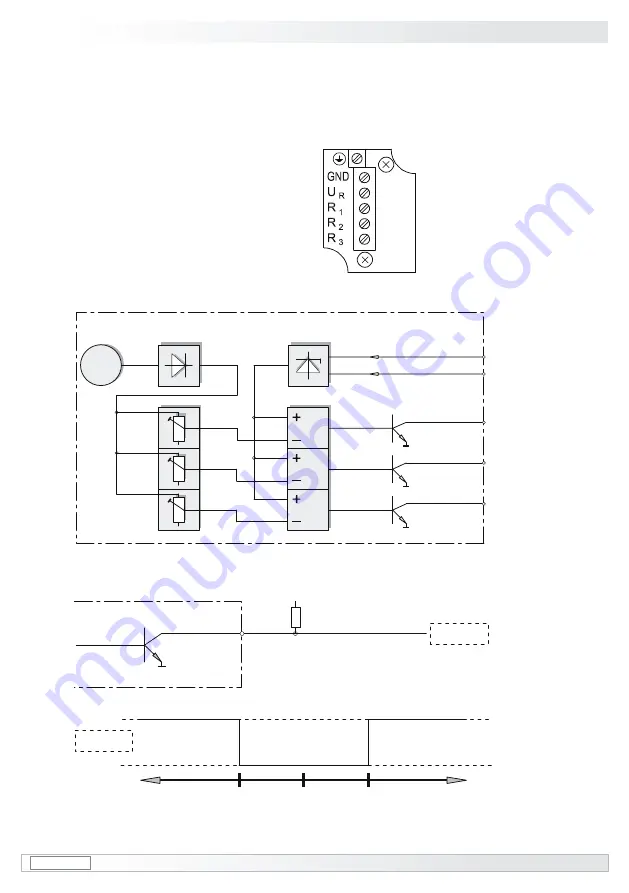
6.4.2

  Ausführung ESL 93  

(3 Relais-Treiber, 3 Schaltdrehzahlen)  

6.4.2.1

  Klemmenbelegung  

6.4.2.2

  Anschlussschaltbild  

6.4.2.3

  Ausgangsschaltverhalten  

6.4.2

  Version ESL 93  

(3 relay driver, 3 switching speeds)  

6.4.2.1

  Terminal assignment  

6.4.2.2

  Circuit diagram  

6.4.2.3

  Manner of output circuit  

Ansicht Y 

Anschlussklemmen

siehe Abschnitt 4.13

View Y 

Connecting terminal

see section 4.13

n  = Drehzahl

/speed


n

s

 = eingestellte Schaltdrehzahl 

/ adjusted switching speed

-n

-n

s

 (1,2,3) 0

+n

s

 (1,2,3)

+n

12 VDC

0 V

out 1/2/3

G

3~

COMP

COMP

COMP

R

1

0 V

0 V

0 V

R

2

R

3

U

R

 = 12 VDC
0 V (GND)

ESL 93

n

1

n

2

n

3

R

1

/R

2

/R

3

0 V

470

12 VDC

ES 93

out 1/2/3

Kabel: 

5-adrig abgeschirmt, 

Länge: max. 200 m 

bei 1 mm

2

 Querschnitt

Cable:


5 leads shielded, 

length: max. 200 m


at 1 mm

2

 cross-section

Summary of Contents for POG 90

Page 1: ...g90 esl_mb 09A1 Montage und Betriebsanleitung Installation and operating instructions POG 90 ESL Kombination Drehimpulsgeber Elektronischer Drehzahlschalter Combination Incremental Encoder Electronic Speed Switch ...

Page 2: ... 10 4 8 Schritt 7 und 8 Klemmenkasten POG 90 11 4 10 Schritt 9 Klemmenkasten POG 90 12 4 11 Schritt 10 Klemmenkasten POG 90 12 4 12 Schritt 11 Klemmenkasten ESL 13 4 13 Schritt 12 Klemmenkasten ESL 13 4 14 Anbauhinweis 14 5 Maßzeichnung 14 6 Elektrischer Anschluss 15 6 1 Klemmenbelegung POG 90 15 6 2 Ausgangssignale POG 90 16 6 3 Kabel HEK 8 Zubehör 16 6 4 Anschluss Drehzahlschalter ESL 17 6 4 1 A...

Page 3: ...0 10 4 8 Step 7 and 8 Terminal box POG 90 11 4 10 Step 9 Terminal box POG 90 12 4 11 Step 10 Terminal box POG 90 12 4 12 Step 11 Terminal box ESL 13 4 13 Step 12 Terminal box ESL 13 4 14 Mounting instruction 14 5 Dimension drawing 14 6 Electrical connection 15 6 1 Terminal assignment POG 90 15 6 2 Output signals POG 90 16 6 3 Cable HEK 8 accessory 16 6 4 Connection speeed switch ESL 17 6 4 1 Versi...

Page 4: ... des Gerätes hängt von den Kugellagern ab die mit einer Dauerschmierung ausgestattet sind 1 4 Der Lagertemperaturbereich des Gerätes liegt zwischen 15 C bis 70 C 1 5 Der Betriebstemperaturbereich des Gerätes liegt zwischen 20 C bis 85 C am Gehäuse gemessen 1 6 EG Konformitätserklärung gemäß Richtlinie 89 336 EWG Artikel 10 sowie Anhang 1 EMV Richtlinie 1 7 Wir gewähren 2 Jahre Gewährleistung im Ra...

Page 5: ...ermanent lubrication 1 4 The storage temperature range of the device is between 15 C and 70 C 1 5 The operating temperature range of the device is between 20 C and 85 C measured at the housing 1 6 EU Declaration of Conformity meeting Council Directive 89 336 EEC art 10 and annex 1 EMC Directive 1 7 We offer a 2 year warranty in accordance with the regulations of the ZVEI Central Association of the...

Page 6: ...alten 2 4 Zerstörungsgefahr durch mechanischen Schock Starke Erschütterungen z B Hammerschläge können zur Zerstörung der Abtastung führen Niemals Gewalt anwenden Bei sachgemäßer Montage lässt sich alles leichtgängig zusam menfügen Für die Demontage geeignetes Abziehwerkzeug benutzen 2 5 Zerstörungsgefahr durch Verschmutzung Schmutz kann in der Kombination zu Kurzschlüssen und zur Beschädigung der ...

Page 7: ...es and or angles are observed 2 4 Risk of destruction due to mechanical shock Violent shocks e g due to hammer impacts can lead to the destruction of the optical sensing system Never use force Assembly is simple when correct procedure is followed Use suitable puller for disassembly 2 5 Risk of destruction due to contamination Dirt penetrating inside the combination can cause short circuits and dam...

Page 8: ... 12 Kabelverschraubung M20x1 5 für Kabel 5 13 mm 1 Housing incremental encoder POG 90 2 Housing mechanical speed switch ESL 3 Solid shaft with key 4x4x20 mm 4 EURO flange B10 5 Terminal box cover POG 90 6 Board with connecting terminal POG 90 see section 4 9 and 6 1 7 Screw with torx and slotted drive M3x10 mm 8 SUB D connectors male on the encoder housing 9 Terminal box cover ESL 10 Connecting te...

Page 9: ...ng K 35 available as accessory see section 4 5 16 Connecting cable HEK 8 available as accessory see section 6 3 17 Connecting cable for ESL 12x 12x 13 14 15 16 17 18 Werkzeugset als Zubehör erhältlich Bestellnummer ET 51 504969 beinhaltet unter anderem 18a bis 18c 18a Torx Schraubendreher Größe TX10 und TX20 oder Torxschlüssel 18b Sechskantschlüssel Größe 2 5 mm bei Verwendung von 15 18c Schrauben...

Page 10: ...abweichungen Vibrationen die die Lebensdauer der Kombina tion verkürzen können The driveshaft should have as less run out as possible because this can otherwise result in an angle error In addition any radial deviation can cause vibrations which can shorten the service life of the combination 4 Montage 4 1 Schritt 1 4 Mounting 4 1 Step 1 siehe Seite 6 see page 6 Größe 2 5 mm Size 2 5 mm zul Anzugs...

Page 11: ...og90 esl_mb 09A1 8 Montage Mounting 4 4 3 Schritt 3 4 4 Schritt 4 4 3 Step 3 4 4 Step 4 siehe Seite 6 see page 6 SW 10 mm 10 mm a f 14 Größe 2 5 mm Size 2 5 mm zul Anzugsmoment Max tightening torque Mt 2 3 Nm 15 ...

Page 12: ...l loading Zulässiger Parallelversatz Admissible parallel misalignment Zulässiger Winkelfehler Admissible angular error Zulässige Axialbewegung Admissible axial movement All dimensions in millimeters unless otherwise stated 0 2 0 05 1 für Ausführung mit isolierender Kunststoffnabe for insulated hub version 0 7 0 3 Der Anbau an den Antrieb muss mit möglichst geringem Winkelfehler und Parallelversatz...

Page 13: ...Mounting 4 4 7 Schritt 6 Klemmenkasten POG 90 4 7 Step 6 Terminal box POG 90 4 6 Schritt 5 Klemmenkasten POG 90 4 6 Step 5 Terminal box POG 90 Größe Size Torx TX20 SW 22 mm 22 mm a f Größe Size Torx TX10 11 12 7 6 siehe Seite 5 see page 5 ...

Page 14: ...lschirm Cable shield Ansicht X siehe Abschnitt 6 1 View X see section 6 1 16 6 siehe Seite 5 oder 6 see page 5 or 6 Zur Gewährleistung der angege benen Schutzart sind nur geeignete Kabeldurchmesser zu verwenden siehe Abschnitt 3 To ensure the specified protection class of the device the correct cable diameter must be used see section 3 ...

Page 15: ...asten POG 90 4 11 Step 10 Terminal box POG 90 4 10 Schritt 9 Klemmenkasten POG 90 4 10 Step 9 Terminal box POG 90 6 7 SUB D Buchse zum Anschluss an POG 90 siehe Abschnitt 4 11 SUB D connector female for connecting to POG 90 see section 4 11 11 5 siehe Seite 5 see page 5 SW 22 mm 22 mm a f Größe Size Torx TX10 Größe Size Torx TX20 12 ...

Page 16: ...r Klemmenkasten Reversible terminal box cover Ansicht Y siehe Abschnitt 6 4 View Y see section 6 4 Zur Gewährleistung der angege benen Schutzart sind nur geeignete Kabeldurchmesser zu verwenden siehe Abschnitt 3 To ensure the specified protection class of the device the correct cable diameter must be used see section 3 Größe Size Torx TX20 SW 22 mm 22 mm a f 11 9 12 siehe Seite 5 see page 5 ...

Page 17: ...s otherwise stated Drehrichtung positiv Positive direction of rotation Montage Maßzeichnung Mounting Dimension drawing 4 5 Wir empfehlen die Kombination so zu montieren dass der Kabelan schluss keinem direkten Wasserein tritt ausgesetzt ist i i We recommend to mount the combi nation in such a manner that the ca ble connection is not directly expo sed to water ...

Page 18: ...X Connecting terminal POG 90 see section 4 10 6 1 2 POG 90 DN I DN TTL DN R 6 1 2 POG 90 DN I DN TTL DN R Zwischen und besteht keine Verbindung There is no connection between and max 1 5 mm2 max AWG 16 Ansicht X Anschlussklemmen POG 90 siehe Abschnitt 4 10 View X Connecting terminal POG 90 see section 4 10 Betriebsspannung nicht auf Ausgän ge legen Zerstörungsgefahr Spannungsabfälle in langen Leit...

Page 19: ...seiltes Kabel Das Kabel sollte in einem Stück und getrennt von Motorkabeln verlegt werden Kabelabschluss Ausführung DN und DN I 1 3 kΩ Ausführung DN TTL und DN R 120 Ω 6 3 Cable HEK 8 accessory Baumer Hübner cable HEK 8 is recom mended As a substitute a shielded twisted pair cable can be used It should have an uninterrupted run with ample clearance to the drive power cable Cable terminating resist...

Page 20: ...6 4 Connection speeed switch ESL 6 4 1 Version ESL 90 1 internal relay 1 switching speed 6 4 1 1 Terminal assignment 6 4 1 2 Circuit diagram 6 4 1 3 Manner of output circuit 6A 250 VAC 1A 48 VDC Ansicht Y Anschlussklemmen siehe Abschnitt 4 13 View Y Connecting terminal see section 4 13 closed 1 2 open 2 3 closed 2 3 open 1 2 closed 2 3 open 1 2 n ns 0 ns n n Drehzahl speed ns eingestellte Schaltdr...

Page 21: ... 4 2 2 Circuit diagram 6 4 2 3 Manner of output circuit Ansicht Y Anschlussklemmen siehe Abschnitt 4 13 View Y Connecting terminal see section 4 13 n Drehzahl speed ns eingestellte Schaltdrehzahl adjusted switching speed n ns 1 2 3 0 ns 1 2 3 n 12 VDC 0 V out 1 2 3 G 3 COMP COMP COMP R1 0 V 0 V 0 V R2 R3 UR 12 VDC 0 V GND ESL 93 n1 n2 n3 R1 R2 R3 0 V 470 12 VDC ES 93 out 1 2 3 Kabel 5 adrig abgesc...

Page 22: ... 15 16 18 19 open 11 12 14 15 17 18 closed 11 12 14 15 17 18 open 12 13 15 16 18 19 closed 11 12 14 15 17 18 open 12 13 15 16 18 19 LED aus out LED aus out LED an on n ns 1 2 3 0 ns 1 2 3 n n Drehzahl speed ns eingestellte Schaltdrehzahl adjusted switching speed 6 4 3 2 Anschlussschaltbild 6 4 3 3 Ausgangsschaltverhalten 6 4 3 2 Circuit diagram 6 4 3 3 Manner of output circuit Höhe 55 mm Kunststof...

Page 23: ...ntage Dismounting 7 7 Demontage 7 1 Schritt 1 7 Dismounting 7 1 Step 1 11 11 7 6 5 9 16 17 Größe Size Torx TX20 Größe Size Torx TX10 Größe Size Torx TX20 SW 22 mm 22 mm a f SW 22 mm 22 mm a f siehe Seite 5 oder 6 see page 5 or 6 12 12 ...

Page 24: ...hritt 2 7 2 Step 2 7 Demontage Dismounting 7 3 Schritt 3 7 3 Step 3 SW 10 mm 10 mm a f Größe 2 5 mm Size 2 5 mm 15 14 siehe Seite 5 oder 6 see page 5 or 6 11 7 11 9 5 Größe Size Torx TX20 Größe Size Torx TX10 Größe Size Torx TX20 12 12 6 ...

Page 25: ...MB154 2 pog90 esl_mb 09A1 22 Demontage Dismounting 7 7 4 Schritt 4 7 4 Step 4 7 5 Schritt 5 7 5 Step 5 Größe 2 5 mm Size 2 5 mm 15 siehe Seite 6 see page 6 ...

Page 26: ...hmoment bei Betriebstemperatur 2 Ncm Belastbarkeit der Welle max axial 250 N radial 350 N Schutzart IP 66 IEC 60529 zulässige Temperatur an der Kombination 20 C 85 C Gewicht 2 5 kg 8 2 Technische Daten Drehimpulsgeber POG 90 Rechteckperioden Umdrehung z 1 024 10 000 je nach Bestellung Ausgabefrequenz f max 250 kHz Logikpegel HTL oder TTL je nach Bestellung Betriebsspannung 9 VDC 30 VDC HTL 5 VDC 5...

Page 27: ...h Eigenversorgung 8 4 Technische Daten Drehzahlschalter ESL Ausführung ESL 93 Schaltdrehzahl n s 3 x 200 5 000 min 1 je nach Bestellung Schaltgenauigkeit 1 500 min 1 4 1 500 min 1 2 Schaltverzögerung 40 ms mit externem Relaismodul ES 93 R 250 ms Drehzahl Hysterese max 30 Ausgang 3 x 40 mA DC Betriebsspannung 12 VDC 10 Stromaufnahme ohne Last 5 mA 8 5 Technische Daten Externes Relaismodul ES 93 R Z...

Page 28: ...emperature 2 Ncm Load on shaft max axial 250 N radial 350 N Protection class IP 66 IEC 60529 Permissible combination temperature 20 C 85 C Weight 2 5 kg 8 2 Technical data Incremental encoder POG 90 Square wave cycles per turn z 1 024 10 000 as precised on order Output frequency f max 250 kHz Logic level HTL or TTL as precised on order Supply voltage 9 VDC 30 VDC HTL 5 VDC 5 TTL 9 VDC 30 VDC TTL v...

Page 29: ...d internally 8 4 General data Speed switch ESL version ESL 93 Switching speed n s 3 x 200 5 000 rpm as precised on order Switching accuracy 1 500 rpm 4 1 500 rpm 2 Switching delay time 40 ms with external relay modul ES 93 R 250 ms Speed hysterisis max 30 Output 3 x 40 mA DC Supply voltage 12 VDC 10 Current consumption at no load 5 mA 8 5 General data External relay modul ES 93 R accessory Relay s...

Page 30: ... 27 pog90 esl_mb 09A1 MB154 2 9 Anhang EU Konformitätserklärung 9 Anhang EU Konformitätserklärung ...

Page 31: ...MB154 2 pog90 esl_mb 09A1 28 9 Appendix EU Declaration of conformity Appendix EU Declaration of conformity 9 ...

Page 32: ...upling K 35 Connecting cable HEK 8 Frequency analogue converter HEAG 121 P Digital converters HEAG 151 HEAG 154 Fiber optic links HEAG 171 HEAG 176 Digital speed switch DS 93 Relay modul ES 93 R Tool kit order number ET 51 504969 10 Zubehör Federscheiben Kupplung K 35 Anschlusskabel HEK 8 Frequenz Analog Wandler HEAG 121 P Digital Konverter HEAG 151 HEAG 154 LWL Übertrager HEAG 171 HEAG 176 Digita...

Reviews: