background image

Specifications – BHG610.5SS 

Product dimensions: 

Aperture dimensions: 

Depth:

510 

mm 

Width:

620 

mm 

Height:

50 mm 

Depth:

480 

mm 

Width:

560 

mm 

Product specifications: 

o

1 x 3.50 kW triple crown (wok) burner

o

1 x 1.75 kW semi-rapid burners

o

1 x 3.00 kW rapid burner

o

1 x 1.00 kW auxiliary burner

o

Front control operation

o

Heavy duty cast iron pan stands

o

Automatic ignition

o

Flame failure safety device on each burner

Standard accessories: 

o

LPG conversion jets

Gas hob surface layout 

1 = 3.50 kW triple crown burner 
2 = 1.75 kW semi-rapid burner 
3 = 3.00 kW rapid burner 
4 = 1.00 kW auxiliary burner 

10

Summary of Contents for BHG300.5SS

Page 1: ...1 User Manual for the BHG300 5SS BHG604 5SS W BHG610 5SS BHG710 5SS BHG900 5SS GAS HOB ...

Page 2: ...nstruction Manual contains important information including safety installation points which will enable you to get the most out of your appliance Please keep it in a safe place so that it is easily available for future reference for you or any person not familiar with the operation of the appliance 2 JW 28 05 12 ...

Page 3: ...ps 16 Cleaning 17 18 Cleaning the hob top 17 After each use 17 Cleaning the hob burners 17 Maintaining the enamelled pan stands 18 Maintaining the cast iron pan stands 18 Installation 19 29 Positioning 20 Unpacking the appliance 21 Installing the appliance 21 Gas connection 23 Ventilation requirements 23 Gas Safety Installation and Use Regulations 24 Gas Adjustment Conversion to LPG 25 Minimum flo...

Page 4: ...Environmental note 4 o The packaging materials that Baumatic uses are environmentally friendly and can be recycled all packaging material with due regard for the environment o Please discard ...

Page 5: ...le to withstand a minimum temperature of 85 C above the room it is located in whilst in use o Certain types of vinyl or laminate kitchen furniture are particularly prone to heat damage or di temperatures below the guidelines given above o Any damage caused by the appliance being installed in contravention the owner o Your new appliance is guaranteed against electrical or mechanical defects subject...

Page 6: ...zones are switched off after use leaning Cleaning of the hob should be carried out on a regular basis appliance it should be disconnected from the mains and cool C o Baumatic strongly recommend that babies and young children are prevented from being near to the appliance and not allowed to touch the applian o If it is necessary for younger family members to be in the kitchen plea o Older children ...

Page 7: ...or installation of this appliance o If the appliance is being used in a Leisure Accommodation Vehicle the requirements of N 721 MUST be followed o Baumatic DOES NOT recommend that this appliance is installed on any type of marine vessel Declaration of conformity This appliance complies with the following European Directives 2006 95 CE General regulations Low tension 2009 142 CE Concerning gas appl...

Page 8: ...h 270 mm Product specifications o 1 x 3 00 kW rapid burner o 1 x 1 00 kW auxiliary burner o Front control operation o Enamelled pan stands o Automatic ignition o Flame failure safety device on each burner Standard accessories o LPG conversion jets Gas hob surface layout 8 1 1 00 kW auxiliary burner 2 3 00 kW rapid burner ...

Page 9: ...kW rapid burner o 2 x 1 75 kW semi rapid burners o 1 x 1 00 kW auxiliary burner o Front control operation o Enamelled pan stands o Automatic ignition o Flame failure safety device on each burner Standard accessories o LPG conversion jets Gas hob surface layout 1 1 75 kW semi rapid burner 2 1 75 kW semi rapid burner 3 3 00 kW rapid burner 4 1 00 kW auxiliary burner 9 ...

Page 10: ...o 1 x 1 75 kW semi rapid burners o 1 x 3 00 kW rapid burner o 1 x 1 00 kW auxiliary burner o Front control operation o Heavy duty cast iron pan stands o Automatic ignition o Flame failure safety device on each burner Standard accessories o LPG conversion jets Gas hob surface layout 1 3 50 kW triple crown burner 2 1 75 kW semi rapid burner 3 3 00 kW rapid burner 4 1 00 kW auxiliary burner 10 ...

Page 11: ...burners o 1 x 1 00 kW auxiliary burner o 1 x 3 50 kW triple crown wok burner o Front control operation o Heavy duty cast iron pan stands o Automatic ignition o Flame failure safety device on each burner Standard accessories o LPG conversion jets Gas hob surface layout 1 1 75 kW semi rapid burner 2 1 75 kW semi rapid burner 3 3 50 kW triple crown burner 4 3 00 kW rapid burner 5 1 00 kW auxiliary bu...

Page 12: ...burners o 1 x 1 00 kW auxiliary burner o 1 x 3 50 kW triple crown wok burner o Front control operation o Heavy duty cast iron pan stands o Automatic ignition o Flame failure safety device on each burner Standard accessories o LPG conversion jets Gas hob surface layout 1 1 75 kW semi rapid burner 2 1 75 kW semi rapid burner 3 3 50 kW triple crown burner 4 3 00 kW rapid burner 5 1 00 kW auxiliary bu...

Page 13: ... mbar Alternative LPG G30 28 30 37 mbar For future reference please record the following information which can be found on the rating plate and the date of purchase which can be found on your sales invoice The rating plate of your hob is located on the underneath of the appliance Therefore it is a good idea to record this information before you install your appliance Model Number Serial Number Dat...

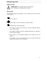
Page 14: ...off Large flame maximum setting ignition position Small flame minimum setting o The minimum setting is at the end of the anti clockwise rotation of the control knob o All operation positions must be selected between the maximum and minimum position o Never select a knob position between the maximum and off position o The symbol on the control panel next to the control knob will indicate which gas ...

Page 15: ... the control knob depressed the automatic ignition for the burner will operate o You should hold down the control knob for 20 seconds after the flame on the burner has lit o After this 20 second interval to regulate the flame you should continue turning the control knob anti clockwise until the flame is at a suitable level The operating position MUST be at a position between the maximum and minimu...

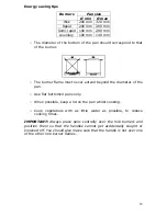
Page 16: ...t never extend beyond the diameter of the pan o Use flat bottomed pans only o When possible keep a lid on the pan whilst cooking o Cook vegetables with as little water as possible to reduce cooking times IMPORTANT Always place pans centrally over the hob burners and position them so that the handles cannot get accidentally caught or knocked off You should also make sure that the handle is not over...

Page 17: ...ooled sufficiently before you attempt to touch them After each use o Remove the pan stands and wipe the appliance over with a soft damp cloth that has been put into warm soapy water The cloth should be wrung out after being taken out of the soapy water o Dry the appliance by rubbing the surface with a soft clean cloth o We would recommend that an appropriate stainless steel cleaner and polish is r...

Page 18: ... has been put into warm soapy water The cloth should be wrung out after being taken out of the soapy water o Using a paper towel thoroughly dry the pan stands Maintaining the cast iron pan stands BHG610 5SS BHG710 5SS BHG900 5SS o IMPORTANT Make sure that the hob surface and pan stands have cooled before you attempt to touch them o Wipe the pan stands over with a soft damp cloth that has been put ...

Page 19: ...ions issued by the Department of Environment o Building Standards Issued by the Scottish Development Department o IEE Wiring Regulations o Electricity at Work Regulations BS 6172 o Installation of Domestic Gas Cooking Appliances if necessary BS 5482 Installation of Domestic LPG Appliances o BS 5440 Installation of Flues and Ventilation for Gas Appliances o Manufacturer s installation Instructions ...

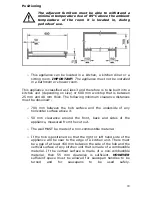
Page 20: ...s must be observed o 700 mm between the hob surface and the underside of any horizontal surface above it o 50 mm clearance around the front back and sides of the appliance measured from the cut out o The wall MUST be made of a non combustible material o If the hob is positioned so that the right or left hand side of the appliance will be near to the edge of a kitchen unit There must be a gap of at...

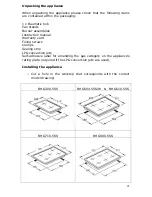
Page 21: ...nstruction manual Warranty card Fixing screws Clamps Sealing strip LPG conversion jets Self adhesive label for amending the gas category on the appliance s rating plate required if the LPG conversion jets are used Installing the appliance o Cut a hole in the worktop that corresponds with the correct model drawing BHG300 5SS BHG604 5SS W BHG610 5SS BHG710 5SS BHG900 5SS 21 ...

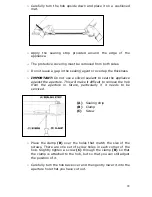
Page 22: ...the aperture This will make it difficult to remove the hob from the aperture in future particularly if it needs to be serviced A Sealing strip B Clamp C Screw o Place the clamp B over the holes that match the size of the screws There are one set of screw holes in each corner of the hob Slightly tighten a screw C through the clamp B so that the clamp is attached to the hob but so that you can still...

Page 23: ...ic Customer Care Department o The hob must be installed by a qualified person in accordance with the current edition of the Gas Safety Installation and Use Amendment Regulations and the relevant building I E E Regulations o Failure to install the appliance correctly could invalidate the manufacturer s guarantee and lead to prosecution under the regulations quoted above o In the UK GASSAFE register...

Page 24: ...ion rules and regulations are followed o The walls behind and near the hob should be resistant to heat steam and condensation o Remember that the quantity of air necessary for combustion must never be less than 2m h for each kW of power see total power in kW on the appliance rating plate Gas Safety Installation and Use Regulations IMPORTANT The appliance MUST be connected to the gas supply by use ...

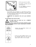
Page 25: ... complies with the gas standards in force o IMPORTANT On completion carry out a gas soundness test Gas adjustment Conversion to LPG All work must be carried out by a GASSAFE registered engineer IMPORTANT Always isolate the hob from the electricity supply before changing the injectors and or adjusting the minimum flow of the burners o Remove the pan stands burners and flame spreaders A o Unscrew th...

Page 26: ...d make sure that the flame spreader is correctly placed on the burner o IMPORTANT The minimum flow adjustment process must be completed before the appliance is next used Minimum flow adjustment for hob gas taps All work must be carried out by a GASSAFE registered engineer IMPORTANT Always isolate the hob from the electricity supply before changing the injectors and or adjusting the minimum flow of...

Page 27: ... be carried out by a GASSAFE registered engineer IMPORTANT Before carrying out any maintenance operations disconnect the appliance from the gas and electricity supplies If a gas tap becomes stiff to operate then you should proceed as follows o Remove the control knobs pan supports burners hob fixing screws and clamps o Remove the hob from the worktop and remove any underside protective covers o Di...

Page 28: ...removing the fixing screws o When fitting a new tap ensure that a new gasket is used o Reconnect the gas tap perform a gas soundness test and then reassemble the hob Electrical connection This appliance must be installed by a qualified person in accordance with the latest edition of the I E E Regulations and in compliance with the manufacturer s instructions Before connecting the appliance make su...

Page 29: ...t your mains supply o Open the box of the supply board o Unscrew the clamp fixing the cable o Replace the cable with one of the same length and in accordance with the specification given above o The green yellow earth wire must be connected to the terminal marked It must be about 10 mm longer than the live and neutral wires o The blue neutral wire must be connected to the terminal marked with the ...

Page 30: ... accessible for the engineer to perform any necessary repair If your appliance is installed in such a way that an engineer is concerned that damage will be caused to the appliance or your kitchen then he will not complete a repair This includes situations where appliances have been tiled in sealed in with sealant have wooden obstructions placed in front of the appliance like plinths Or any install...

Page 31: ...31 ...

Page 32: ...6 Bennet Road Reading Berkshire RG2 0QX United Kingdom Customer Care Telephone 0844 692 3605 Spares Telephone 0844 692 3606 Website www baumatic co uk ...

Page 33: ...33 ...

Page 34: ...34 ...

Page 35: ...35 ...

Page 36: ...cod 1 008 89 0 www baumatic co uk ...

Reviews: