A
B
C
D
Te chnic al e quipm en t
KDK rota ry drive
Sta nda rd
Integ rated k elly damping s yste m
–
Wear pad s e xcha ngea ble without
–
removal o f rotary driv e
Ex changeab le kelly dr ive ad apter
–
Ex changeab le kelly dr ive k eys
–
2 sele ctab le mo des o f operation
–
Trigg er plate
–
Uni-dire ctio nal impa ct f unc tion o n KD K
–
Opt iona l
Ca rdanic joint (fo r cas ing i nsta lla tion)
–
KD K 110 SL (f o r high effec tiv e spin off ),
–
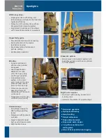
Fig. A
Main winch
Sta nda rd
Hyd ra ulic ally c on trolled f ree wheeling
–
Automat ic rop e tens ioning fac ilit y
–
Swivel alignment f unction
–
Depth measuring d evice o n main rope
–
Ele ctro nic load se ns ing
–
Winch drum with spe cial gr oo ving
–
Transpare nt ring fo r eas y oil che ck
–
Pin c onnec tion
–
BG at tachment
Sta ndard
Bauer H-kine mat ic s yst em
–
Crowd cylind er ups ide-down
–
Crowd in f ast and slo w mo de
–
Hoist limi t swit ch on m ain and aux iliary
–
winc hes
Swiv el fo r main rope
–
Pivote d anchor p oints f or main and
–
auxiliary ropes
Two ma st s ectio ns w it h pin jo int
–
Optiona l
Auxiliary winch 65 kN / 14,610 lbf ,
–
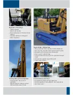
Fig. B
Swiv el fo r auxiliary rope
–
Ce ntral lubr ication syste m
–
Upper kelly g uide (hy dr aulica lly
–
ope ra ted)
Bauer Se r vic e Kit
–
(Quick-release c ou pler s o n hydra ulic
hoses,
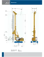
Fig. C
, S peed m eas uring d evice
on ro tar y dr ive, Diagnostic p anel and
mano me ter s fo r hydraulic funct ions ,
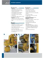
Fig. D
)
Low head conv ert ib le,
–
Fig. E
BG 11 H


