


Installation & Maintenance Manual: BRBAC 1 HP
Published December 2019
Rev.A1
19
5
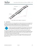
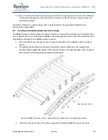
Installation
The installation supervisor on site should have the elevation and layout prints with detailed information
regarding the placement of conveyor sections and support structures. This information is not the
responsibility of ZiPline Conveyor to provide unless otherwise specified.
1.
Clear the workspace around the portion of the layout selected for installation.
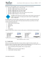
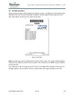
2.
Ensure that the conveyor and accessory skids containing the correct BRBAC mark number are
unpacked and all components are accounted for.
3.
Measure out from the constrained origin to start placement of supports. It is recommended that
snap chalk lines are used, or other methods of keeping a consistent line.
4.
Use the elevation layouts to determine the conveyor top of conveyor surface and the
incline/decline angle of a mark section.
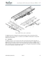
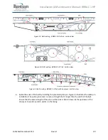
5.
Place the support type that the layout designates. Each support type has a corresponding mark
sticker.
6.
Check the flow direction on the mark stickers to ensure that conveyor is mounted properly.
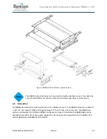
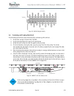
7.
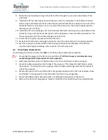
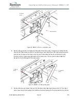
Place the conveyor onto the support structure and fasten 3/8”
-16 carriage bolts and serrated
flange nuts. Torque the serrated flange nuts to 31 ft-lb.
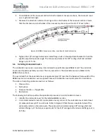
8.
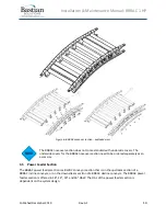
Refer to Section 5.5 to install and adjust the angle of the noseover section.
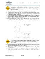
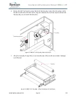
Do not lift the drive section of the conveyor using the lifting lug on the AC motor and
gearbox. This will cause damage to the gearbox and drive pulley. Use any mounting
point at the corners of the drive section.
9.
Check for straightness and level of the conveyor sections. See instructions in section 5.2.
10.
Route the supplied AC belt through the assembled conveyor. See instructions in section 5.3.
11.
Attach any applicable accessories and connecting hardware to the mounted conveyor section.
12.
Check that the upstream and downstream heights of the conveyor section agree with the
system layout instructions.
13.
Secure the supports to the floor (or other permanent fixture).
ZiPline Conveyor does not provide hardware for attaching floor supports to the floor
or other permanent surface.
The floor supports of the installed BRBAC conveyor section must be permanently
secured prior to operation. Failure to do so can cause damage to the equipment and
injure personnel in the area. Please take necessary precautions during install.
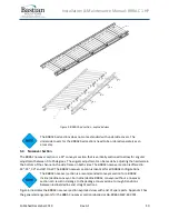
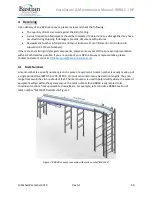
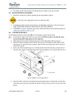
5.1
Floor Support Location
When locating the floor support locations on site, ZiPline Conveyor recommends reviewing the
guidelines outlined in Bastian Solutions ZiPline Conveyor - Support Installation Manual.
There are two floor supports between the power feeder and the tail section. If you have a floor support
missing, contact your ZiPline conveyor representative.
Summary of Contents for BRBAC 1 HP
Page 1: ...Installation and Maintenance Manual Model BRBAC 1 HP Effective December 2019 Rev A1...
Page 44: ...Installation Maintenance Manual BRBAC 1 HP Published December 2019 Rev A1 44...
Page 45: ...Installation Maintenance Manual BRBAC 1 HP Published December 2019 Rev A1 45...
Page 46: ...Installation Maintenance Manual BRBAC 1 HP Published December 2019 Rev A1 46...
Page 47: ...Installation Maintenance Manual BRBAC 1 HP Published December 2019 Rev A1 47...