


Camera Interface
Basler L301kc
2-11
DRAFT
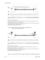
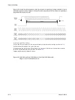
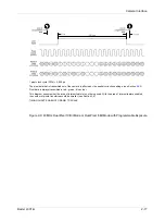
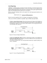
Figure 2-4 shows the data sequence when the camera is operating in edge-controlled or level-
controlled exposure mode. Figure 2-5 shows the data sequence when the camera is operating in
programmable exposure mode.
Figure 2-4: 20 MHz 8 Bit RGB Mode with Edge or Level Controlled Exposure
1 pixel clock cycle (PClk) = 0.05 µs
The pixel data that is transmitted out of the camera is affected by the spatial correction settings.
(see Section
This diagram assumes that the area of interest feature is not being used. With the area of interest feature enabled,
the number of pixels transferred could be smaller. (see Section
TIMING CHARTS ARE NOT DRAWN TO SCALE
Summary of Contents for L301kc
Page 1: ...Basler L301kc USER S MANUAL Document Number DA00051806 Release Date 13 July 2007...
Page 4: ......
Page 14: ...Introduction 1 6 Baslert L301kc DRAFT...
Page 20: ...Camera Interface 2 6 Basler L301kc DRAFT Figure 2 3 Camera Frame Grabber Interface...
Page 102: ...Configuring the Camera 4 32 Basler L301kc DRAFT...
Page 116: ...Troubleshooting 6 10 Basler L301kc DRAFT...
Page 118: ...Revision History ii Basler L301kc DRAFT...
Page 120: ...Feedback iv Basler L301kc DRAFT...
Page 124: ...Index viii Basler L301kc DRAFT...