Operation and Features
Basler L301kc
3-1
DRAFT
3 Basic Operation and Features
3.1
Functional Description
The
L301
kc
is a high resolution camera which employs a tri-linear CCD-sensor chip designed for
color scanning. The tri-linear sensor contains three lines of photosensitive elements (pixels) with
2098 pixels per line. One line is covered with a red filter, one line with a green filter and one line
with a blue filter to provide spectral separation.
Exposure time is normally controlled via an externally generated trigger signal (ExSync). The
ExSync signal facilitates periodic or non-periodic pixel readout.
When exposure is controlled by an ExSync signal, exposure time can be edge-controlled, level-
controlled, or programmable. In edge-controlled mode, charge is accumulated over the full period
of the ExSync signal and a rising edge of ExSync triggers the readout of accumulated charges
from the sensor elements to the CCD shift registers. In level-controlled mode, charge is
accumulated when the ExSync signal is low and a rising edge of ExSync triggers the readout of
accumulated charges. In programmable mode, exposure time can be programmed to a
predetermined period. In this case, exposure begins on the rising edge of ExSync and
accumulated charges are read out when the programmed exposure time ends.
A free-run mode that allows the camera to operate without an ExSync signal is also available. In
free-run mode, the camera generates its own internal control signal and the signal is used to
control exposure and charge readout. When operating in free-run, the camera outputs lines
continuously.
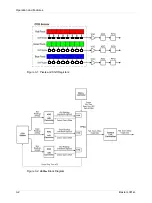
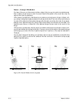
At readout, accumulated charges are transported from each line of pixels to a separate shift
register (see Figure 3-1). As charges move out of the shift registers, they are converted to voltages
proportional to the amount of accumulated charge. The shifts are clocked according to the
camera’s internal data rate.
The voltages moving out of each shift register are amplified by a Variable Gain Control (VGC) and
then digitized by a 10 bit, Analog-to-Digital Converter (ADC).
Depending on the spatial correction settings, the digitized data from the first two color channels is
held in a temporary memory (FIFO) until the corresponding data for the third channel arrives (see
Section
). When the red, green and blue information for the first pixel is complete, the digitized
video data is transmitted from the camera to the frame grabber using a format compatible with the
Camera Link standard (see Section
for details).
For optimal digitization, gain and offset are programmable via a serial port.
Summary of Contents for L301kc
Page 1: ...Basler L301kc USER S MANUAL Document Number DA00051806 Release Date 13 July 2007...
Page 4: ......
Page 14: ...Introduction 1 6 Baslert L301kc DRAFT...
Page 20: ...Camera Interface 2 6 Basler L301kc DRAFT Figure 2 3 Camera Frame Grabber Interface...
Page 102: ...Configuring the Camera 4 32 Basler L301kc DRAFT...
Page 116: ...Troubleshooting 6 10 Basler L301kc DRAFT...
Page 118: ...Revision History ii Basler L301kc DRAFT...
Page 120: ...Feedback iv Basler L301kc DRAFT...
Page 124: ...Index viii Basler L301kc DRAFT...


