2-2 BE1-50/51B-229
Controls
and Indicators
9252000892 Rev A
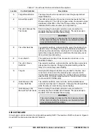
Table 2-1. Front Panel Control and Indicator Descriptions
Locator Control/Indicator
Description
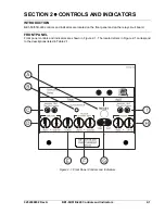
A
Target Reset Button
The target reset button is pressed to reset the gravity-latched
target indicators.
B
Active/Pickup LED
The LED turns red when the sensed current exceeds the Time
Pickup setting (H). The LED turns green when the sensed current
decreases below 95% of the Time Pickup setting. A green LED
indicates that the relay is active, but not picked up.
C
Time (51) Manual Trip
Test Jacks
Short-circuiting the test jacks provides a secure method to
manually trip the controlled circuit breaker. The jacks accept a
standard 0.08 inch diameter banana plug.
WARNING!
Trip circuit voltage is present at the front panel test jacks.
When short-circuiting the test jacks, use insulated jumpers
to avoid contact with this voltage.
D
Time Dial Switches
Two selector switches, units and tenths, select the desired char-
acteristic curve. A setting of 0.0 gives instantaneous operation
without any intentional delay. A setting of 9.9 corresponds to the
typical time delay provided by an electromechanical relay set at
its maximum time dial setting.
E
Curve Switch
This switch selects one of nine inverse time functions or one
fixed time function.
F
Time (51) Pickup
Switches
Two selector switches, units and tenths, set the time overcurrent
pickup level in amperes. Changing the pickup setting while the
relay is in service may cause tripping.
G
Targets
Gravity-latched target indicators are provided for the time over-
current (51) function and the instantaneous overcurrent (50)
function. Red targets latch when the corresponding overcurrent
element trips. For proper target operation, the trip circuit current
must exceed 200 milliamperes.
H Instantaneous
(50)
Pickup Switches
Two selector switches, tens and units, set the instantaneous
overcurrent pickup level in amperes. Changing the pickup setting
while the relay is in service may cause tripping.
I Instantaneous
(50)
Manual Trip Test Jacks
Short-circuiting the test jacks provides a secure method to
manually trip the controlled circuit breaker. The jacks accept a
standard 0.08 inch diameter banana plug.
WARNING!
Trip circuit voltage is present at the front panel test jacks.
When short-circuiting the test jacks, use insulated jumpers
to avoid contact with this voltage.
CIRCUIT BOARD
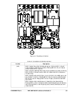
Circuit board controls consist of control switch assembly SW3. The location of SW3 is shown in Figure 2-
2 and SW3 functions are described in Table 2-2.
Summary of Contents for BE1-50/51B-229
Page 2: ......
Page 6: ...iv BE1 50 51B 229 Introduction 9252000892 Rev A This page intentionally left blank ...
Page 8: ...vi BE1 50 51B 229 Introduction 9252000892 Rev A This page intentionally left blank ...
Page 10: ...ii BE1 50 51B 229 General Information 9252000892 Rev A This page intentionally left blank ...
Page 20: ...ii BE1 50 51B 229 Controls and Indicators 9252000892 Rev A This page intentionally left blank ...
Page 26: ...ii BE1 50 51B 229 Functional Description 9252000892 Rev A This page intentionally left blank ...
Page 30: ...ii BE1 50 51B 229 Installation 9252000892 Rev A This page intentionally left blank ...
Page 34: ...4 4 BE1 50 51B 229 Installation 9252000892 Rev A This page intentionally left blank ...
Page 36: ...ii BE1 50 51B 229 Testing 9252000892 Rev A This page intentionally left blank ...


