


5-2
BE1-40Q Setting and Testing
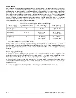
Primary current
"
(single
!
phase primary var)
3
V
LL
"
(13.33 Mvar)
3
12800
"
1804 A
(4.2)
Secondary current
"
primary current
CT ratio
"
1804
5000/5
"
1.8A
(4.3)
Pickup
"
V
relay
3
×
I
relay
"
120
3
×
1.8
"
125
"
Low Range, TAP position E (Table 1
!
1)
(4.4)
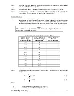
Step 2.
Determine the desired primary current.
Step 3.
Specify a BE1-40Q Relay having a nominal sensing range of 120 V
LL
(for a PT ratio of 12800/120).
Step 4.
Determine the desired secondary current.
Step 5.
Determine the pickup.
OPERATIONAL TEST PROCEDURE
BE1-40Q Loss of Excitation Relays operation and calibration can be verified by the following operational test
procedure. Test results obtained from this procedure may not fall within specified tolerances because of
inaccuracies in test equipment. When evaluating results, consider the inherent error of the test equipment.
Test equipment should be accurate within one percent or better.
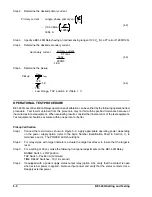
Pickup Verification
Step 1.
Connect the test circuit as shown in Figure 5-2. Apply appropriate operating power, depending
on the power supply option (refer to the Style Number Identification Chart in Section 1), to
terminals 3 and 4. The POWER LED should light.
Step 2.
For relay styles with target indicators, actuate the target reset lever to insure that the target is
reset.
Step 3.
For a setting of 25 var, make the following front panel adjustments on the BE1-40Q Relay:
RANGE Switch - LOW position
TAP Switch - Position A (minimum)
TIME DELAY Switches - 10 (1.0 second)
Step 4.
If equipped with a power supply status output relay (option 2-S), verify that the contact is open
when external power is applied. Remove input power and verify that the status contacts close.
Reapply external power.
Summary of Contents for BE1-40Q
Page 13: ...2 2 BE1 40Q Human Machine Interface Figure 2 1 Location of Controls and Indicators ...
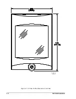
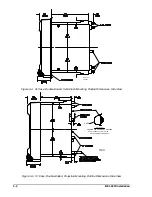
Page 19: ...4 2 BE1 40Q Installation 2 02 01 D1427 01 Figure 4 1 S1 Case Outline Dimensions Front View ...
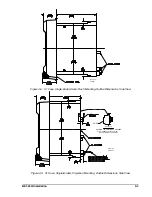
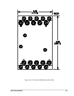
Page 22: ...BE1 40Q Installation 4 5 Figure 4 6 S1 Case Outline Dimensions Rear View ...
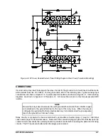
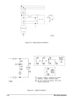
Page 25: ...4 8 BE1 40Q Installation Figure 4 10 Sensing Input Connections Figure 4 11 Output Connections ...
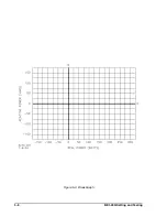
Page 35: ...5 8 BE1 40Q Setting and Testing Figure 5 4 Blank Graph ...