


1-6
BE1-40Q General Information
Target Indicators
Function targets may be specified as either internally operated, or cur-
rent operated by a minimum of 0.2 ampere through the output trip
circuit. When current operated, the output circuit must be limited to 30
amperes for 0.2 seconds, 7 amperes for 2 minutes, and 3 amperes
continuously.
Radio Frequency
Maintains proper operation when tested for interference in accordance
Interference (RFI)
with IEEE C37.90.2-1987,
Trial-Use Standard Withstand Capability of
Relay Systems to Radiated Electromagnetic Interference from
Transceivers.
Isolation
In accordance with IEC 255-5 and ANSI/IEEE C37.90-1989 one minute
dielectric (high potential) tests as follows:,
All circuits to ground:
2121 Vdc.
Input to output circuits:
1500 Vac or 2121 Vdc.
Shock
In standard tests, the relay has withstood 15 g in each of three mutually
perpendicular planes without structural damage or degradation of perfor-
mance.
Vibration
In standard tests, the relay has withstood 2 g in each of three mutually
perpendicular planes, swept over the range of 10 to 500 Hz for a total of six
sweeps, 15 minutes each sweep, without structural damage or degradation
of performance.
Surge Withstand Capability
Qualified to ANSI/IEEE C37.90.1-1989,
Standard Surge Withstand
Capability (SWC) Tests for Protective Relays and Relay Systems.
UL Recognition
UL Recognized per Standard 508, UL File No. E97033. Note: Output
contacts are not UL Recognized for voltages greater than 250 volts.
Fast Transient
Qualified to ANSI/IEEE C37.90.1-1989.
Standard Surge Withstand
Capability (SWC) Tests for Protective Relays and Relay Systems.
Operating Temperature
-40
°
C (-40
°
F) to +70
°
C (+158
°
F).
Storage Temperature
-65
°
C (-85
°
F) to +100
°
C (+212
°
F).
Weight
13.5 pounds (6.12 kg) maximum.
Case Size
S1. (Dimensions are provided in
Section 4, Installation.)
Summary of Contents for BE1-40Q
Page 13: ...2 2 BE1 40Q Human Machine Interface Figure 2 1 Location of Controls and Indicators ...
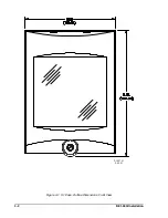
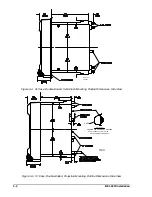
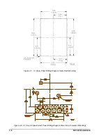
Page 19: ...4 2 BE1 40Q Installation 2 02 01 D1427 01 Figure 4 1 S1 Case Outline Dimensions Front View ...
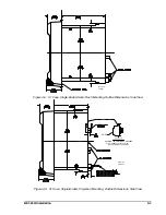
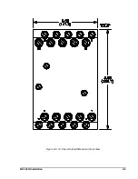
Page 22: ...BE1 40Q Installation 4 5 Figure 4 6 S1 Case Outline Dimensions Rear View ...
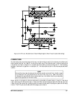
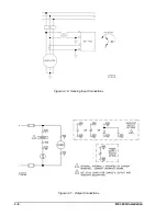
Page 25: ...4 8 BE1 40Q Installation Figure 4 10 Sensing Input Connections Figure 4 11 Output Connections ...
Page 35: ...5 8 BE1 40Q Setting and Testing Figure 5 4 Blank Graph ...