9424200772 Rev D
3
BE1-11
Quick Start Guide
Figure 1. Front Panel Label Example for BE1-11
f
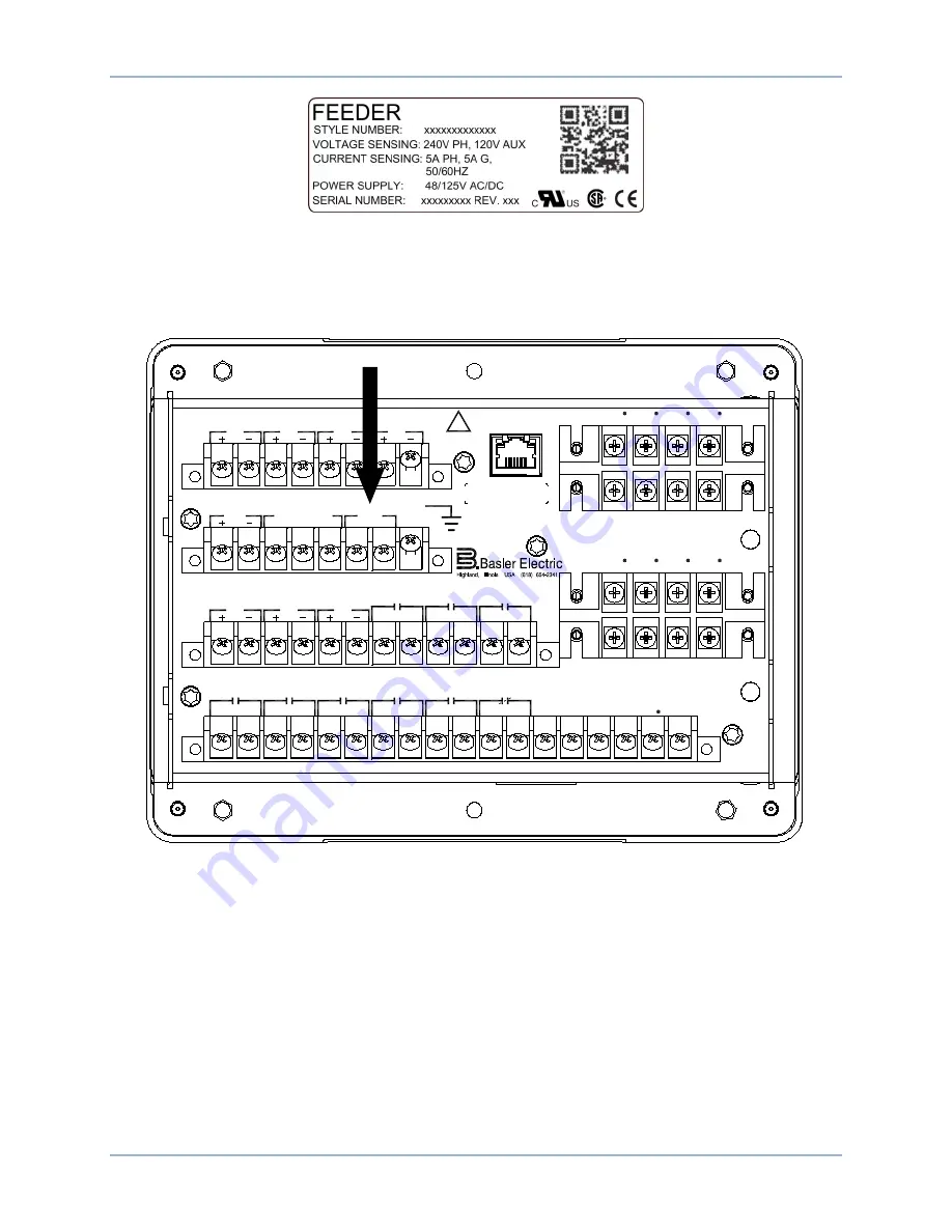
Connect rear terminals A6, A7, and A8 (ground) to a power supply. Figure 2 shows the rear terminals of
the BE1-11 in a J type case with standard I/O option. Figure 3 shows the rear terminals of the BE1-11 in
an H or P type case (BE1-11
f
, BE1-11
i
, and BE1-11
g
only). Apply operating power consistent with the
nominal power supply values listed on the front-panel label. Wait until the boot sequence is complete.
Figure 2. PWR Rear Terminals (J Type Case with Standard I/O Option)
ETHERNET
!
WARNING
BE1-11
C12
C11
C10
C9
C8
C7
C6
C5
C4
C3
C2
C1
C13
C14
C15
C16
C17
C18
V
A
OUT 2
OUT 3
OUT 4
OUT 5
OUT 1
ALARM
V
B
V
C
V
X
V
X
N
E12
E11
E10
E9
E8
E7
E6
E5
E4
E3
E2
E1
OUT 8
OUT 7
IN5
IN6
IN7
OUT 6
A8
A7
A6
A5
A4
A3
A2
A1
IRIG
PWR
C
A
B
COM2 RS-485
GND
B8
B7
B6
B5
B4
B3
B2
B1
IN1
IN2
IN3
IN4
D1
D3
D5
D7
IA1
IB1
IC1
IG1
IA1
D2
D4
D6
D8
IB1
IC1
IG1
IA2
F2
F4
F6
F8
IB2
IC2
IG2
F1
F3
F5
F7
IA2
IB1
IC2
IG2
P0061-43
Summary of Contents for BE1-11f
Page 1: ...QUICK START GUIDE FOR BE1 11 Protection Systems Publication 9424200772 Revision D May 17 ...
Page 2: ......
Page 6: ...iv 9424200772 Rev D Contents BE1 11 ...
Page 20: ...14 9424200772 Rev D Quick Start Guide BE1 11 ...
Page 22: ...16 9424200772 Rev D Revision History BE1 11 ...
Page 23: ......


