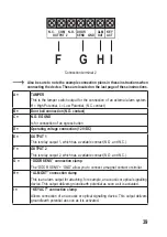
F G H I
N.C. COM N.O.
OUTPUT 2
DOOR
SENS GND
ALM
OUT
KEY
ACT
Connection terminal 2
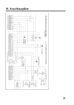
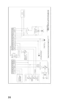
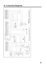
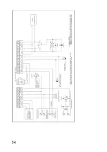
Also be sure to note the example connection plans in these instructions when
connecting the device. These are located on the last page of these instructions.
A =
TAMPER
This is the tamper switch output for the connection of an external alarm system.
H = High Potential, L = Low Potential, (N.C. contact)
B =
Door bell connection (N.O. contact)
C =
N.O. EG GND
Is for connection of an egress button
D =
Operating voltage connection (12 V/DC)
E =
OUTPUT 1
This is relay output 1, which has a variable contact (N.O. and N.C.).
F =
OUTPUT 2
This is relay output 2, which has a variable contact (N.O. and N.C.).
G =
“DOOR SENS” connection clamp
The “DOOR SENS” + “GND” allow you to connect a magnet contact or similar.
H =
“ALM OUT” connection clamp
This is an alarm output for attaching, for example, an acoustic or optical signalling
device. This output delivers ground/earth potential as soon as it is activated.
I =
“KEY ACT” connection clamp
Allows connection of an acoustic or optical signalling device. This output delivers
ground/earth potential as soon as it is activated.
39
Summary of Contents for 1833947
Page 27: ...14 Anschlusspl ne 27...
Page 28: ...28...
Page 53: ...14 Connection Diagrams 53...
Page 54: ...54...
Page 82: ...14 Plans lectriques 82...
Page 83: ...83...
Page 111: ...14 Aansluitschema s 111...
Page 112: ...112...
Page 115: ......

