Base Line Cloud Network BL-CLOUD-WFE Installation And Configuration Manual Download Page 21

21

866 294 5847      |     baselinesystems.com     |     [email protected]

BASELINE CLOUD NETWORK MODULE-CONFIGURATION GUIDE:  BASESTATION 1000, FLOWSTATION, SUBSTATION

1.  Plug an Ethernet cable into the Ethernet 

port on the back of the controller board 

and plug the other end of the cable into a 

live Ethernet jack. 

2.  On the controller, press  

System Setup

The System Setup menu displays.

3.  Press ↓ to highlight the 

Network Setup 

option and then press 

OK 

to select it. The 

Network Setup menu displays.
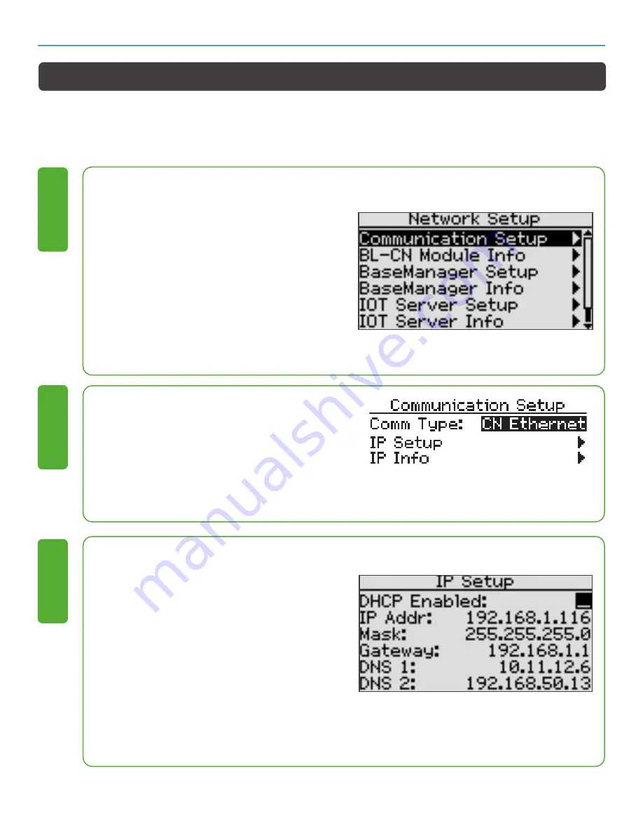
4.  The 

Communication Setup

 option should 

be highlighted. If it is not, press ↓ or↑ to 

highlight it. 

1

1.  Press 

OK.

 The Communication Setup 

screen displays. 

2.  In the Comm Type field, press + or – to 

select CN_Ethernet.

2

1.  Press ↓ to select IP Setup. 
2.  Press

 OK.

 The IP Setup screen displays. 

3.  In the 

DHCP Enabled

 field, press + or - to 

remove the checkmark. 

4.  Press ↓ to highlight the first digits in the IP 

Addr field. Press  ← or → to move the digits 

that you want to change. Press + or -  to 

change the value in the field. 

5.  Press  ↓ to move to the othe fields you 

need to change. Complete the fields for 

IP Address, Mask, Gateway, and Preferred 

DNS Server. Ask your administrator for the 

settings.

3

Setting Up a Static Ethernet Connection

A static IP Ethernet connection is a permanent IP address that does not change. In some cases, 

private network configurations or network security issues might require that you configure a static IP 

address for your controller.

Summary of Contents for Cloud Network BL-CLOUD-WFE

Page 1: ...ar Materials Provided Cloud Network Module Antenna with cable 5 pin serial cable Zip Ties Tools Needed Phillips screwdriver Crescent wrench Needle nose pliers We recommend that you back up your curren...

Page 2: ...ud Network Module Diagrams 3 Installing the Cloud Network Module into an X XS cabinet 4 7 Installing the Cloud Network Module into a pedestal cabinet 8 13 Configuration Guide for the BaseSation 3200 1...

Page 3: ...nector for the Wi Fi antenna not used for cell configuration C Ethernet connector D Reset switch and status LED E Cell module with antenna cable adaptor When receiving the Cloud Network Module inspect...

Page 4: ...ted before beginning If the module is powered up with a loose or disconnected antenna damage may occur to the circutry This damage is not covered by warranty 1 Power down the controller 1 Use needle n...

Page 5: ...m of the antenna and then thread the nut onto the stem Use a wrench to tighten the nut sufficiently to ensure that the antenna makes good contact with the outside of the cabinet 4 Thread the coax conn...

Page 6: ...n the Cloud Network Module with the posts on the cabinet Use the screws provided to securely attach the unit inside the cabinet 7 Plug the 5 pin connector from the Cloud Network Module into the Comm 2...

Page 7: ...Power up the controller 11 Installing the Cloud Network Module into an X XS Cabinet Cont 1 For Cell Modem connections attach the cable from the antenna to the antenna cable port on the Cloud Network M...

Page 8: ...2 Remove the plastic cap the nut and the lock washer from the stem of the antenna 1 Put the stem of the antenna through the mounting hole on the top of the antenna riser so the antenna is positioned...

Page 9: ...the nuts from the bolts that secure the cover to the outside wall Set the nuts aside to be replaced in a later step 3 Remove the bolts that are holding the cover on the outside wall Set the bolts asi...

Page 10: ...hat you made in the gasket and into the inside of the pedestal 2 Working from the outside of the pedestal insert the bolts that you removed earlier into the four holes Working from the inside of the p...

Page 11: ...ed up with a loose or disconnected antenna damage may occur to the circuitry The damage is not covered by warranty 10 With the WI FI antenna on the bottom side of the Cloud Network Module align the th...

Page 12: ...oller board Note If another connector is attached to the upper 5 pin terminal block disconnect it and then reconnect it to the Comm 2 connector 12 Installing the Cloud Network Module into a Pedestal C...

Page 13: ...tems com BASELINE CLOUD NETWORK MODULE Installing the Cloud Network Module into a Pedestal Cabinet Cont 1 Replace the pedestal door and then restart the controller BaseStation 1000 Press the RUN butto...

Page 14: ...Communication Setup screen displays 2 In the Comm Type field press or to select CN_Ethernet 2 Setting Up a CN Ethernet Connection A Cloud Network CN Ethernet connection allows your controller or devi...

Page 15: ...ress Enter The Communication Setup screen displays 2 In the Comm Type field press or to select CN_Ethernet 2 1 Press Next to select IP Setup 2 Press Enter The IP Setup screen displays 3 In the IP Addr...

Page 16: ...t press Next until it is highlighted 1 1 Press Enter The Communication Setup screen displays 2 In the Comm Type field press or to select CN_Cell 2 Press Next to select Cell Status then Enter to view T...

Page 17: ...er to search for the network The asterisks represent signal strengths as indicated below Maximum level signal strength Middle level signal strength OK level signal strength 4 1 Press or to highlight t...

Page 18: ...hted If it is not Press Next until the Communication Setup option is highlighted 1 1 Press Enter The Communication Setup screen displays 2 In the Comm Type field press or to select CN_Wi Fi 2 1 Press...

Page 19: ...NFIGURATION GUIDE BASESTATION 3200 In the Find Network field press Enter to search for the network 4 1 Press or to highlight the desired network then Enter to select it 5 Setting Up a CN Wi Fi Connect...

Page 20: ...start your controller or device it retrieves a new IP address 1 Press to select IP Setup 2 Press OK The IP Setup screen displays The controller uses the Dynamic Host Configuration Protocol DHCP to est...

Page 21: ...tion Setup screen displays 2 In the Comm Type field press or to select CN_Ethernet 2 1 Press to select IP Setup 2 Press OK The IP Setup screen displays 3 In the DHCP Enabled field press or to remove t...

Page 22: ...menu displays 3 The Communication Setup option should be highlighted If it is not press or to highlight it 1 1 Press OK The Communication Setup screen displays 2 In the Comm Type field press or to sel...

Page 23: ...OK to select it The Network Setup menu displays 3 The Communication Setup option should be highlighted If it is not press or to highlight it 1 1 Press OK The Communication Setup screen displays 2 In t...

Page 24: ...list of networks will diisplay Bars next to each network represent signal strength 4 bars Maximum level signal strength 2 bars Middle level signal strength 1 bar OK level signal strength 4 1 Press or...

Page 25: ...baselinesystems com Copyright 2020 HydroPoint Data Systems Inc All rights reserved CUSTOMER SUPPORT support baselinesystems com Toll free 866 294 5847 Fax 208 323 1834 RevA070220...

Reviews: