background image

April 2012 

DSST Installation Guide, Rev. 5 

 Page 7 of 10


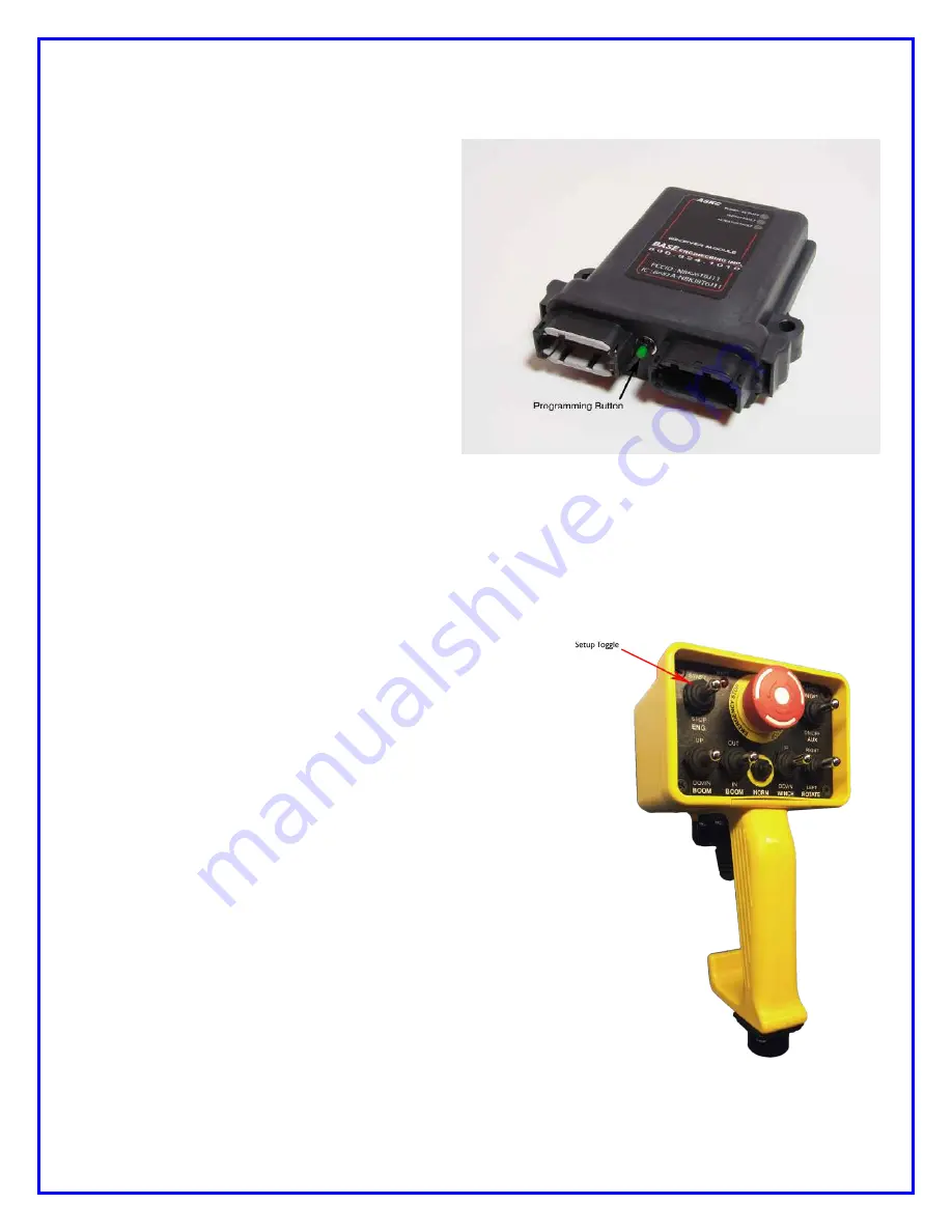
b. Press the programming button on the receiver quickly 2 times. The blue LED

should blink 2 times in confirmation. If pressed the incorrect number of times, the
middle red LED will blink quickly 3 times. Repeat this step.

c. The minimum speed can

now be adjusted by the
SETUP toggle on the
handheld (top left position of
the faceplate). Each press
UP of the toggle will increase
the minimum speed by 3%,
up to a maximum of 40% of
maximum speed (100%).
Each press DOWN of the
toggle will decrease the
minimum speed by 3%, to a
minimum of 0% of maximum
speed (100%).

d. The Receiver will update the

new value after there has been no activity on the SETUP toggle for 3 seconds.
There should be a brief flash of the middle red LED after the update is
completed.

e. Testing can now be done to verify if the adjustments are correct. This can be

done by activating a function on the
handheld and observing the results.
As the minimum speed is increased,
the joysticks/trigger will become
more responsive. If more
adjustments need to be done, go
back to step 4c.

f.

Once adjustments have been
completed, press the programming
button on the receiver quickly 3
times. The blue LED should blink 3
times, stay solid for approximately 1
second, then blink 3 more times.
Changes made are now permanent.

5. Adjusting maximum speed (maximum

attainable speed when the
joystick/trigger is fully displaced):

a. Press the programming button on

the receiver quickly 3 times. The
blue LED should blink 3 times in
confirmation. If pressed incorrectly,
the middle red LED will blink 4
times. Repeat this step.

b. Press the programming button on the receiver quickly 3 times. The blue LED

should blink 3 times in confirmation. If pressed the incorrect number of times, the
middle red LED will blink 3 times. Repeat this step.

Summary of Contents for FHSTP Series

Page 1: ...INSTALLATION AND OPERATING INSTRUCTIONS DSST SYSTEM PROPORTIONAL and NON PROPORTIONAL TOGGLE SWITCH RADIO REMOTE CONTROL SYSTEM MODEL FHSTP DSSTP SERIES...

Page 2: ...e handheld unit is a robust custom designed pistol grip unit It uses a combination of toggle switches and speed control trigger to allow variable speed proportional machine control note non proportion...

Page 3: ...user presses any function toggle on the handheld unit the blue LED light on the receiver will also begin to flash and continue to do so as long as the function toggle is pressed This light does not bl...

Page 4: ...rge is getting low the unit should be recharged as soon as possible To charge the batteries unscrew the protective cap on the bottom of the handheld and connect the small plug of the supplied charger...

Page 5: ...shipped from the factory configured and ready for operation It is recommended that the handheld unit be charged before it is put into operation E Stop ON OFF button The E Stop ON OFF button must be in...

Page 6: ...ss the green push button located near the grey connector on the receiver 5 times quickly The blue LED will flash 5 times Press the button once more The blue LED will flash once go solid then flash 8 m...

Page 7: ...now be done to verify if the adjustments are correct This can be done by activating a function on the handheld and observing the results As the minimum speed is increased the joysticks trigger will b...

Page 8: ...red press the programming button quickly 15 times after receiver startup The blue LED will flash 15 times Factory speed defaults are now restored and any previous changes are lost System Troubleshooti...

Page 9: ...handheld is not proportional make sure the green enable button is pressed before activating a toggle switch Blue LED flashes when the handheld is operated but function pressed does not activate or ac...

Page 10: ...art 15 of the FCC Rules Operation is subject to the following two conditions i This device may not cause harmful interference and ii This device must accept any interference received including interfe...

Page 11: ...ON OFF BLACK WHITE BOOM DOWN WHITE BOOM UP YELLOW BOOM IN PURPLE BOOM OUT GRAY WINCH UP DK BROWN WINCH DOWN DK BLUE START YELLOW BLACK ROTATION RT ORANGE ROTATION LEFT GREEN E STOP RED BLACK 16 PIN P...

Page 12: ......

Reviews: