background image


2. 

ESSENTIAL OPERATING PRACTICE 

Gas-Explorer detectors are easy to use. A detector is turned on by pressing the left button; 

its operation is controlled by three 

“Soft”

 buttons whose function is shown on the display. The 

middle button toggles 

“Mute” 

on and off in the Track Gas mode (see later).  Double-clicking the 

middle  button  turns  the  backlight  continuously  ON,  or  OFF  depending  on  its  previous  state.  
Once the appropriate display is  selected, operation is  automatic.  However, a few  general  rules 
must be followed to insure reliability. 

Pump.

  Gas-Explorer detectors have a built-in pump and depend on this pump for their 

operation.  If the pump is not functioning normally, the instrument will not function properly.  It 
is therefore essential to check the pump each time the instrument is turned on. 

Pump  Test:

    Connect  the  probe  you  plan  to  use  and  turn  the  instrument  on.    After  the 

display shows “

Block Intake

”, block the probe tip with your finger to show 

"Pump OK"

.   

If 

"Pump  OK"

  does  not  appear,  tighten  all  connections  and  repeat  the  test.    If  a  block 

condition is still not observed, remove the probe and block directly the inlet to the instrument.  If 

"Pump OK"

 still does not appear, return the instrument for repair.  

A pump test can be carried out as above at any time during normal operation. If there is 

any indication that the pump is not operating normally, return the instrument for repair. 

Filters.

    Dust  and  water-block  filters  protect  the  sensors  and  the  pump  from  dust  and 

accidental intake of liquid water.  Just as a car would not be operated without air and fuel filters, 
do  not  operate  a  detector  without  a  filter  on  the  probe. 

Operation  without  this  filter  will 

eventually degrade the natural gas sensor and the pump. It also voids the limited warranty.


Filters  are  available  from  Bascom-Turner  in  packages  of  five,  Part  No.  WF-505  for  all  models 
except WF-705 for EGA-611/612. 

Zero  Check.

    All  sensors  drift  to  some  extent  over  time.    Sensor  drift  is  automatically 

corrected by zeroing if the drift is within 0.1% vol. GAS (and 10ppm CO if the unit is equipped 
with a CO sensor).  If the drift is outside this limit, “

NO GO

” is displayed and the user is asked 

to  autozero  the  unit  in  “clean”  outdoor  air.    The  user  can  override  this  limit  and  re-zero  the 
instrument unless the zero has drifted over 1.0% vol. GAS, in which case the instrument should 
be checked by a trained professional (the sensor may need replacement).  It is important that the 
zero adjustment be done in clean air, for example, outdoors.  If the sampled gas is not clean, a 
systematic error may be introduced in subsequent measurements. 

WARNING: 

On a call, turn the instrument on outdoors, not indoors.  


Test  and  Calibration.

    Gas-Explorer  detectors  must  be  checked  and  calibrated 

periodically with gas of known composition.  The catalytic combustion,  carbon monoxide, and 
hydrogen  sulfide  sensors  depend  on  catalysts  which  may  loose  activity  or  get  poisoned  during 
use.  When this happens, there will be diminished response. 

The necessary frequency of calibration depends on actual use and on the concentration of 

catalyst poisons in the sampled gas.  This concentration is, or course, not generally known.  

A detector can be tested with "bump" gas.  Such tests verify that the gas sensor(s) are in 

operating condition.  To verify and adjust, if necessary, their sensitivity they must be calibrated.   

A  detector  can  be  automatically  calibrated  in  approximately  one  minute  using  Bascom-

Turner's  calibration  gas  (2.5%  CH

4

  and  100  ppm  CO  in  air).    Given  the  ease  and  speed  of 

automatic  calibration,  it  pays  to  calibrate  as  frequently  as  possible,  and  certainly,  no  less  than 
monthly. 


            2. 

Summary of Contents for GAS-EXPLORER OM-0517

Page 1: ...BASCOM TURNER INSTRUMENTS GAS EXPLORER DETECTORS OPERATION MANUAL NATURAL GAS CARBON MONOXIDE OXYGEN HYDROGEN SULFIDE Part Number OM 0517...

Page 2: ...dise authorization RMA number must be obtained prior to returning a detector to Bascom Turner A detector returned to Bascom Turner with probe and water block filter shipping prepaid will be repaired c...

Page 3: ...erference from Other Gases Liquids or RFI 8 6 Change of Batteries 9 7 Probes 10 8 Routine Maintenance 11 PART 2 SETUP CALIBRATION AND ALARM LEVEL SELECTION 1 Setup Parameters 13 2 Further Setup Parame...

Page 4: ...ods by User and Unit ID Office Reports Accuracy CH4 2 of reading 20ppm 0 C to 40 C 0 1 to 5 vol 2 0 from 5 to 100 vol CO 5 of reading 10 ppm H2S 5 of reading 1ppm O2 0 2 vol Resolution GAS 20 ppm from...

Page 5: ...can be calibrated with System Gas Measurements Over the Full Range of Gas The instruments detect methane over the full range of methane concentrations up to 100 GAS Peak and current readings are disp...

Page 6: ...air flue gas and gases given off by appliances A detector alerts the user acoustically and visually by flashing the symbol s for the detected gas es whose concentration exceeds preset limits Visual a...

Page 7: ...r and the pump It also voids the limited warranty Filters are available from Bascom Turner in packages of five Part No WF 505 for all models except WF 705 for EGA 611 612 Zero Check All sensors drift...

Page 8: ...etected Safety These instruments measure the concentration of natural gas in air and give more generally an indication of the presence of other combustible gases When used by trained personnel they co...

Page 9: ...days from the date of the last calibration and an opportunity to calibrate see Part 2 Calibration If calibration is not required the instrument proceeds to enter the operational mode Monitor see below...

Page 10: ...Gas is retrained and displayed until another mode of operation is chosen or a new zero is obtained or the unit is turned off Bar Holing The detector may be used to measure gas levels in sampling holes...

Page 11: ...when about 90 of its purple material has changed color to brown or when it gets clogged or flooded see Accessories and Spare Parts Flue Gas Filter Part No FF 005 and Purple Beads and Spare Retaining...

Page 12: ...Pump Check for Tight Connections To check for tight connections block the probe inlet to observe Flow Blocked on the display If Flow Blocked fails to appear there may be a leak WARNING The instrument...

Page 13: ...nductivity from air examples are hydrogen helium carbon dioxide other hydrocarbons Gases or vapors which may interfere with carbon monoxide detection include substances which can be electrochemically...

Page 14: ...line C cells 3 Insert two fresh C size alkaline batteries 4 Replace the battery cap and give it one quarter turn battery cap bar vertical Note that the batteries are inserted with the positive termina...

Page 15: ...dge directly to the sample hose always use a dust and water block filter WARNING Hold the probe without touching the metal while it is in the flue and immediately afterwards Running the instrument in...

Page 16: ...lter IF 705 Removal of the intake connector used to attach the sampling hose of the detector exposes a metal filter pressfit onto the intake These filters are not a substitute for dust and water block...

Page 17: ...ilter material to bottom of threads and place the plastic retainer disk flat on top of the filter material Screw in top until finger tight and check seal with block tests CAUTION Do not remove or punc...

Page 18: ...om 5 to 60 seconds factory setting is 15 seconds Air Free CO Detectors with both CO and Oxygen sensors may be set to display CO on an air free basis This choice displays the concentration of CO in a g...

Page 19: ...Calibrating for about a minute and then changes to Calibration OK with a display of readings taken while sampling calibration gas or Does Not Calibrate if calibration was unsuccessful Three tries are...

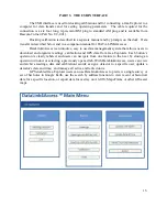
Page 20: ...ystem that allows users to download and organize readings calibration and GPS data from Gas Explorers Each button s operation is clearly labeled and users can navigate from one feature to the next by...

Page 21: ...sensors Percent LEL 0 100 Percent O2 0 40 vol Percent GAS 0 100 vol PPM CO 0 2000 ppm Note LEL readings are only recorded in detector models ending in 201 301 321 411 and 611 Standard 100 LEL 5 GAS O...

Page 22: ...tationed User s name is the name or number of the person using the detector or when the unit is retired and the reason why it is retired i e Lost Last assigned date and time is changed each time a new...

Page 23: ...Reports submenu This submenu has two tables listing units by unit ID with each table providing different information about the units The tables can be scrolled independently of each other by left cli...

Page 24: ...Assignment History by Unit ID is a list of each time when a unit s assigned user is changed Whenever the Unit Edit button is used to change a unit s assignment there is a date and time stamped record...

Page 25: ...e and unscrewing the four screws which secure the pump gasket pump plate diaphragm and piston to the manifold Usually replacing the pump plate is sufficient to restore operation Reverse the process fo...

Page 26: ...Figure 4 Gas Explorer with top of case and main circuit board removed...

Page 27: ...S 001 Replacement Dust Filters 5 pkg DF 105 Flue Gas Filter 5 pkg FF 005 Extended Duty Flue Gas Filter 5 pkg FF 105 Heavy Hydrocarbon Filter 5 pkg HF 005 Inlet Filter Quick Connect Air Intake 5 pkg IF...

Page 28: ......

Reviews: