E 5110RS / 116526W
E 7110RS / 116528W
E10110RS / 116531W
Original-Gebrauchsanleitung
V2/0319
Page 1: ...E 5110RS 116526W E 7110RS 116528W E10110RS 116531W Original Gebrauchsanleitung V2 0319...
Page 2: ...iew of parts 62 5 Installation and operation 64 5 1 Instructions for the installer 64 5 1 1 Installation instructions 64 5 1 2 Installation place 65 5 1 3 Preparing for Installation 65 5 1 4 Electrica...
Page 3: ...essible for anyone carrying out the installation servicing maintenance or cleaning Please keep these instructions and give them to future owners of the device 1 Safety This device is designed in accor...
Page 4: ...This symbol highlights recommendations and information aimed for effective and trouble free device operation 1 2 Important safety instructions The device is not intended for use by individuals includi...
Page 5: ...r These can be dangerous for the user or lead to damages of the device or personal injury and further the warranty expires To prevent hazards and to ensure optimum efficiency no modifications or alter...
Page 6: ...et hands or while standing on the wet floor Disconnect the device from the power supply when the device is not used in the case of interruptions during the operation of the device before cleaning the...
Page 7: ...steamer or appropriate base it is not recommended to use the higher guides preventing looking into the container Due to safety reasons after positioning the device place the sticker Hot liquid in the...
Page 8: ...TION This device has been designed and built for commercial use and can be operated in kitchens by the qualified personnel only The operational safety of the device is assured only in case of proper u...
Page 9: ...by violation of advice concerning operation and cleaning use other than designed alterations made by user use of inadequate spare parts We reserve the right to make technical changes for purposes of...
Page 10: ...er The outer and inner packing material should be removed completely from the device before installation If you liked to dispose the packing consider the regulations applicable in your country Supply...
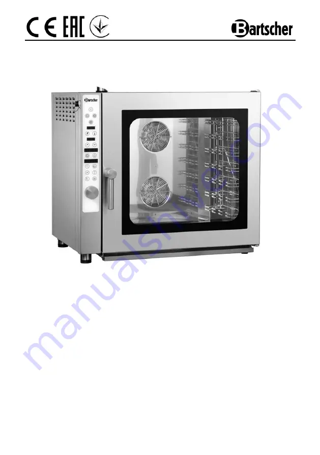
Page 11: ...table steam outlet Steamer chamber illumination Useful transverse GN guide LED temperature time steam cooking and internal temperature display Possibility of using the internal temperature sensor 1160...
Page 12: ...ed food per guide max 10 kg Total amount of cooked food max 25 kg Temperature range 50 C 280 C Power supply 6 3 kW 400 V 3 NAC 50 Hz Water connection 3 4 Water pressure max 3 bar Dimensions W 890 x D...
Page 13: ...ide max 10 kg Total amount of cooked food max 35 kg Temperature range 50 C 280 C Power supply 9 6 kW 400 V 3 NAC 50 Hz Water connection 3 4 Water pressure max 3 bar Dimensions W 890 x D 815 x H 815 mm...
Page 14: ...on 3 4 Water pressure max 3 bar Dimensions W 890 x D 815 x H 1010 mm Weight 125 2 kg Includes 1 grate 1 1 GN 1 tray 1 1 GN 1 water supply hose 1 PVC drainpipe 1 supply hose for cleaning agent We reser...
Page 15: ...mer Made of chromed brass 3 4 connector Initial setting at 3 bar adjustable from 1 to 6 bar Input pressure max 16 bar Maximum working temperature 65 C Code no 533051 1 pair of standardised rails for b...
Page 16: ...t includes plastic can 5l pump fixing elements 2 connecting hoses 150 cm can pump 80 cm pump moisturing pipe Code no 116011 Connecting set for combi steamer M E Compact solution for large kitchens The...
Page 17: ...Rail format 1 1 GN 600 x 400 mm Rail type longitudinal Feet adjustable height 745 mm to 790 mm Dimensions W 950 x D 700 x H 745 mm Weight 24 kg Code no 115079 4 3 Overview of parts Description of dra...
Page 18: ...63 1 3 6 2 9 5 8 4 11 12 13 15 14 16 17 10 7...
Page 19: ...ility for personal injuries or material damages resulting from the failure to observe the aforementioned regulations or tampering with single components of the device or using non original spare parts...
Page 20: ...to ensure good air circulation Install the device in such manner that the rear part is easily accessible in order to allow the electricity and water connections and maintenance Never place the device...
Page 21: ...r installation of the device may result in injuries Prior to installation compare specification of the local power network with the technical specifications of the device see nameplate Connect the dev...
Page 22: ...ring connection to the new system drain sufficient amount of water before connecting the device to the water network to prevent penetration of impurities to the magnetic valves Connect included hose a...
Page 23: ...ber Drain pipe must be connected with use of appropriate hose 22 mm and led to the drain system 5 1 7 Connecting supply hose for cleaning agents The supply hose for cleaning agents is permanently conn...
Page 24: ...requirements must be met to approve the oven for the use The oven light is turned on by pressing the corresponding button and turns off automatically after 45 seconds if it has not been turned off ea...
Page 25: ...e food containers or other objects during and after cooking can be very high be highly attentive in handling in order to avoid burns Grasp them only with suitable protective gloves Danger of burns Avo...
Page 26: ...stallation of the device the label Hot liquid in container Danger of burns which is located in the package must be attached to the combi steamer at a height of 1 6 m from the floor 5 2 2 Operation Cle...
Page 27: ...d setting T 10 Steam generation setting T 11 Activate Deactivate cooking and pre heating phases T 12 Programming T 13 Steam extractor T 14 Internal light button T 15 Cancel button Cleaning T 16 START...
Page 28: ...ressing T 6 button or using M dial The selected temperature is displayed on LED D 1 The device will automatically pass to the time setting mode T 8 button flashes The desired time is set by turning M...
Page 29: ...T 6 button or using M dial The selected temperature is displayed on LED D 1 The device will automatically pass to the time setting mode T 8 button flashes Set the desired time turning dial M and then...
Page 30: ...button flashes Set the desired time turning dial M and then confirm your selection pressing button T 8 or dial M The selected time is displayed on LED D 2 The device will automatically pass to the fa...
Page 31: ...ure sensor C into the opening provided Release the red detent B To remove the probe press the detent B again pull the core temperature sensor C and release the detent B Push the plug A in again CAUTIO...
Page 32: ...d temperature is displayed on LED D 1 The device will automatically pass to the time setting mode The time set cannot be set now but you have to select cooking baking with CORE TEMPERATURE SENSOR by p...
Page 33: ...weight loss of the food is reduced To activate Delta T T working mode press button T 5 If the button flashes select the desired temperature difference between the cooking temperature and internal temp...
Page 34: ...closed by pressing T 13 button When the steam extractor aligns itself T 13 button flashes no other task can be executed To open the steam extractor change the position of T 13 button ON STEAM EXTRACTO...
Page 35: ...M Turn dial M to the right in order to return to programming the recipe If we activate the cooking programme by pressing buttonT 16 the LED displays D 3 and D 4 will read PRE and HEAT After pressing T...
Page 36: ...lay D 4 will show the number of the first free programme in memory e g if 3 programmes are already saved in pos 1 2 and 3 the first free place in memory will display as PRG 04 Press and hold for sever...
Page 37: ...the oven In this case the oven will not pre heat even if it is included in the program Changing deleting a cooking baking program To introduce changes to a saved programme select the number of the des...
Page 38: ...ogram select cooking phase 1 STEP1 then press and hold button T 11 until the LED D 4 display reads dEL N Turn dial M to the left When the LED D 4 display reads dEL Y press the dial The LED D 4 display...
Page 39: ...hut off when the baking chamber cools by approx 40 C If the desired temperature in the baking chamber is still not reached repeat the entire process The exhaust automatically opens when this function...
Page 40: ...f burns During preparation of food or liquids in the containers pay attention to the possible spillage either during cooking or during removing the container from the chamber It is not recommended to...
Page 41: ...appropriate cleaning agents Rinse the compartment thoroughly with clean water and ensure no residue remains Dry the cooking compartment o Use only special stainless steel cleaning agents as inappropri...
Page 42: ...cate NORMAL medium or STARK intensive depending on the device chamber contamination level o After selecting the appropriate program press T16 button Start The automatic cleaning begins Cleaning begins...
Page 43: ...o stop cleaning or T12 to continue When cleaning is to be continued after interrupting the device switches automatically to the previous cleaning phase o Before new baking cycle rinse the device chamb...
Page 44: ...Turn the locks clockwise fig o Open the inner glass fig o Clean both sides of the inner glass and the door of the device using relevant cleaning agents o Do not use aggresive or abbrasive cleaning age...
Page 45: ...y and close the water supply Wait to let the device cool down o Before moving the device to another place make sure that the power supply and water supply are correctly disconnected o If the device is...
Page 46: ...bove solutions contact customer service The ventilator stops working while the device is in use Turn the device off and wait until the motor overheating safety device turns itself on again Check if ve...
Page 47: ...spose of electric devices with household waste When the device may not be longer used each consumer is obliged to dispose of the device at the dedicated local collection point separately from househol...