


Installation
POLARIS PROFESSIONAL
- for Zone 2 / 22
POLARIS Panel PC Professional 15" up to 24"
32/66
Technical data subject to change without notice..
08/2019
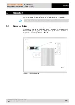
5.6.3
Ethernet terminal assignment
Configuration Ethernet
Terminal Interface
Signal
Remarks
X13
Ethernet
RxD +
10BaseT Receive
positive
X14
Ethernet
RxD -
10BaseT Receive
negative
X15
Ethernet
TxD +
10BaseT Transmit
positive
X16
Ethernet
TxD -
10BaseT Transmit
negative
Assignment RJ45 plug for Ethernet to POLARIS Panel PC terminal block
Connection RJ45
POLARIS
PIN
Signal
Terminal
1
TX+
X13
2
TX-
X14
3
RX+
X15
4
not used
5
not used
6
RX-
X16
7
not used
8
not used
5.6.4
RS422 interface
Configuration RS422
Terminal Interface
Signal
Remarks
X17
X18
Termination
On/Off
Jumper between terminal X17 and
X18 for activation of the terminator
resistors
X19
Interface COM 1 TxD B (TxD+) Transmission cable
Input
X20
Interface COM 1 TxD A (TxD-)
Transmission cableI
Input
X21
Interface COM 1 RxD B (RxD+) Receiving cable
Input
X22
Interface COM 1 RxD A (RxD-) Receiving cable
Input
Connection PLC with RS422 interface to POLARIS.
Maximum length of the data line 1,000 m.
PIN 1
PIN 8
Summary of Contents for POLARIS B7-72V1 Series
Page 6: ...blank...