S900C Series
Installation Instructions
10070218 REV 3 - 09/19
3
800-533-3948 www.barronltg.com
Surface Ceiling or Surface Wall Mount
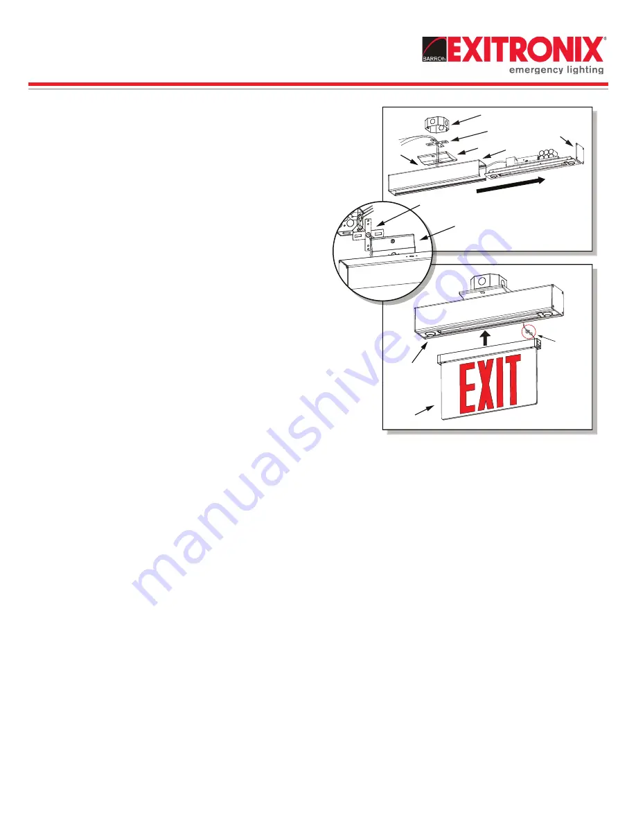
1. Attach the adjustable crossbar to the J-box using the (2) 8-32 x 1”
screws (supplied). Use the slotted portion of the adjustable crossbar
to mount to the J-box and position such that the portion with the
threaded holes is facing out from the J-box (Fig. 1).
2. Punch out the desired knockouts located in the top or side of the
housing for ceiling or wall mounting, respectively. Insert the plastic
grommet (supplied) into the center hole.
3. Attach the canopy to the housing using the (2) M4 x 8mm
screws (supplied).
4. Insert the (2) plastic rivets (supplied) into the (2) unused M4
holes in the housing.
5. Remove one of the housing end plates and set aside. Slide out the
trim plate assembly from the housing.
6. Connect the battery/batteries to the PCB.
7. Slide the trim plate assembly partially into the housing so that the wires
can be routed through the canopy, then route the wires through the
canopy.
8. Slide the trim plate assembly fully into the housing and remove the
excess slack from the wires inside the housing by pulling them farther
out through the canopy. Replace the end plate and secure with the
(4) screws.
9. Make electrical connections; see
Electrical Connections
section.
10. Secure the unit to the adjustable crossbar using the (2) M4 x 40mm screws (supplied). Ensure the canopy is securely
fastened against the ceiling or wall and will not rotate.
11. Connect the EXIT panel assembly to the PCB, then secure by sliding into the EXIT panel slot in the trim plate (Fig. 2).
Remote Lamps
If the unit is installed with the remote capable option, the unit can support 3.6VDC 3W max. remote capabilities.
Compatible with two RL1 remote lamps (non-G2 models) or one RL1 remote lamp (G2 models).
To connect the remote head(s) to the unit:
1. Remove the jumper, if present, and discard.
2. Connect the remote wires to the remote connector. Yellow is positive (+) and purple is negative (-).
3. Plug the remote connector into the female connector on the PCB labeled Lamp 3.
Fig. 2
Lamp Heads
EXIT Panel
Connector
EXIT Panel
J-box
Adjustable Crossbar
Canopy
Enclosure
End Cap
Top Mount
Fig. 1
J-box
End Cap
Wall Mount
Adjustable
Crossbar


