background image

System Sanitization

After sanitization is complete (approximately 3.5 hours),
place the unit into its normal (recirculation) mode to allow
the system to recirculate overnight after cleaning.

1.

From the (Idle) mode, press the UP or DOWN
arrow until the display reads, “Sanitize Unit?”

2.

Press ENTER.

3.

Display will prompt, “Disconnected Inlet Water
(NO).”

4.

Disconnect feed water supply at the quick-dis-
connect inlet valve.

5.

Press the UP or DOWN ARROW to select (YES)
and then press ENTER. Display will now
prompt, “Injected Sanitant (NO)?”

6.

Remove solution syringe from wrapper.

7.

Open front (left side) door. Remove luer cap on
system  injection port, located on the right side
of the cartridge pack manifold by turning coun-
terclockwise.

8.

Remove the syringe luer cap and attach the 
syringe to the system luer fitting.

9.

Slowly inject the solution into the system and
remove syringe. Avoid injecting air into system.

10. Replace luer cap on injection port. Close door.

11.

Press the UP or DOWN arrow to select (YES)
and then press ENTER. Display will now read,
“Reconnected Water (NO).” 

12. Attach feed water supply removed in step 4.

13. Press the UP or DOWN arrow to select (YES)

and press ENTER. Display will now read, “Unit
Sanitizing.”

37

M

AINTENANCE AND

S

ERVICING

Note
The sanitization timer will display after
six months, reminding you to sanitize
the unit. Complete the system saniti-
zation procedure and reset the saniti-
zation timer according to the
“Resetting the Sanitization Timer” sec-
tion in this manual. 

Warning
Disconnect from the power supply
prior to maintenance and servicing.

Warning
Avoid splashing disinfecting solution
on clothing or skin.

Ensure all piping connections are tight
to avoid leakage.

Ensure adequate ventilation.

Carefully follow manufacturer’s safety
instructions and material safety data
sheets.

This device to be used with water
feeds only.

Sanitizing/cleaning agents must be
used in compliance with instructions in
this manual. Failure to comply with the
above could result in explosion and
personal injury.

Warning
Refer servicing to qualified personnel.

Summary of Contents for NANOpure DIamond Analytical

Page 1: ...BARNSTEAD THERMOLYNE NANOpure DIamond Analytical ultrapure water system Operation Manual Series 1190 Model No Voltage D11901 100V 240V LT1190X1 6 22 00...

Page 2: ...nt 23 Resetting the Sanitization Timer 24 Setting Volumetric Dispensing 25 Setting Timed Dispensing 26 Performing a System Flush 26 Changing Purity Units 26 Temperature Compensation 27 Installing Floa...

Page 3: ...l outlet of correct voltage and current handling capacity 2 Do not locate the NANOpure DIamond Analytical directly over equipment that requires electrical service Routine maintenance of this unit may...

Page 4: ...akage 5 Ensure adequate ventilation 6 Carefully follow manufacturer s safety instructions on labels of chemical containers and material safety data sheets 7 Depressurize system prior to removing the c...

Page 5: ...resistiv ity of up to 18 2 megohm cm Water resistivity is continu ously monitored by a resistivity cell and displayed on a digital display The electronics can be verified and calibrated utilizing a N...

Page 6: ...ed to 100 psig 7kg cm2 maximum Temperature Range 4 C 40 C 40 104 F TDS CaCO3 70 ppm Silica 1 ppm Silt 5 SDI Product Water Water Quality Resistivity 18 0 m cm TOC Less than 10 ppb Flow Rate 1 5 lpm max...

Page 7: ...Limits for Harmonic Current Emissions EN 61000 3 3 Limits for Voltage Fluctuations and Flicker EN 61326 1 Electrical Equipment for Measurement Control and Laboratory Use Part I General Requirements Sa...

Page 8: ...discarding Put the NANOpure DIamond Analytical on a bench Sanitization Cartridge CMX25 Wall Bracket Unit Wall Bracket Remote Display BC1190X10 Accessory Parts Bag Includes Feed Water Tube 3 8 O D Drai...

Page 9: ...nstruction as well as fastener type must be considered when mounting this unit The mounting surface and fasteners selected must be capable of supporting a minimum of 150 lbs 68 kg Inadequate support a...

Page 10: ...ch side of the wall bracket out as far as they will go 6 Hang the unit on the wall bracket by sliding the mounting pins into the wall bracket slots 7 Push the locking slides on each side of the wall b...

Page 11: ...ght of the unit Remove the protective black cover and store it for future use if the control panel is returned to the top cover 6 Locate the 10 ft 3 1 m 25 pin M F cable included with the unit attach...

Page 12: ...e the Installing a Float or Pressure Switch section for more information Atmospheric Drain Connection When the NANOpure DIamond Analytical flushes the water used is sent to drain through this connecti...

Page 13: ...f the system status as follows LED is not illuminated System is OFF or in Idle mode Solid Green LED System is recirculating and operating normally Blinking Green LED System is in Standby mode Red LED...

Page 14: ...e User Settings section of this manual for information UP and DOWN arrows allow you to scroll between menu options items and values BACK allows you to return to the previous menu option item Please no...

Page 15: ...rtridge Pack Installation 1 Open front left side door Turn the cartridge pack so the caps are facing you Remove the caps 2 Verify that each of the four posts on the car tridge pack has an o ring 3 Lif...

Page 16: ...witch to the I ON position 7 The system greeting will display the type of unit you own This greeting is Base 8 The system electronics will initialize and check its calibration All units have been fact...

Page 17: ...move luer cap on system injection port located on the right side of the cartridge pack manifold by turning counterclockwise 8 Remove syringe luer cap and attach syringe to the system luer fitting 9 Sl...

Page 18: ...Remove the new 0 2 micron filter and bell assembly from the bag and insert it into the dis penser arm manifold Gently turn it clockwise until it is fully seated 18 Remove the protective cap from the...

Page 19: ...set to OFF This feature is accessible only from the normal recirculating mode when the display is showing purity 1 Place a container under the dispenser 2 Press DISPENSE Water will start dispensing im...

Page 20: ...BACK until you return to the Idle mode Setting the Displayed Language 1 From the Idle mode when display reads NANOpure DIamond Idle xx xx xx xx xx xx press the BACK switch until the dis play reads LA...

Page 21: ...When prompted with Set Time press the UP or DOWN arrow to choose Yes then press ENTER This is to set the time of day 10 Press the UP or DOWN arrow until you reach the desired hour value Press ENTER 1...

Page 22: ...Menu 7 Press ENTER 8 Proceed through the options by pressing ENTER until Set Cell Constant is displayed 9 Press the UP or DOWN arrow to select Yes 10 Press ENTER 11 Note that the digits are entered f...

Page 23: ...P to return to the recirculating mode Selecting the Set Point The NANOpure DIamond Analytical electronics include a user programmable set point which alerts you when water quality falls below the prog...

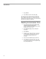
Page 24: ...en the display reads NANOpure DIamond Idle xx xx xx xx xx xx press the UP or DOWN arrow until the display reads Reset Timers 2 Press ENTER Display will read Reset UV Timer NO 3 Press ENTER 4 Display w...

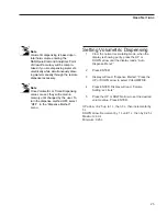
Page 25: ...Press ENTER UP arrow 0 25 up to 1 L then 5 L then incremental by 5 L DOWN arrow Decrement by 1 L until 1 L then by 0 25 L Maximum 60 L Minimum 0 25 L Note Volumetric dispensing is based upon total flu...

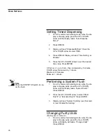
Page 26: ...ow 1 up to 5 min then increments by 5 minutes DOWN arrow Decrement by 1 minute Maximum 40 minutes Minimum 1 minute Performing a System Flush 1 From the normal recirculating mode when the dis play is s...

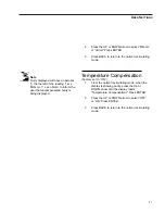
Page 27: ...the display is showing purity press the Up or DOWN arrow until the display reads Temperature Compensation Press ENTER 2 Press the UP or DOWN arrow to select OFF or ON Press ENTER 3 Press BACK to retur...

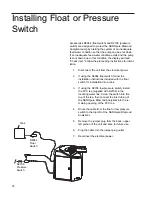
Page 28: ...ation instructions included with the float switch for installation into a tank 3 If using the D2706 low pressure switch install the PVC tee supplied with D2706 in the incoming water line Screw the swi...

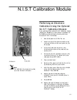
Page 29: ...N I S T calibration module to the connection point J2 To Outlet Cell on the calibration board PC1190X2 5 Close and latch door 6 Reconnect the power cord and turn the unit on by depressing the main pow...

Page 30: ...he main power switch to the OFF O position Unplug the unit 13 Remove the calibration module and reconnect the cell 14 Reattach the cover plate and close and latch the door 15 Reconnect the power cord...

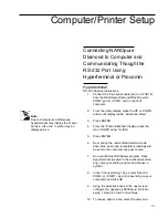
Page 31: ...g the normal Recirculation mode date time purity and temperature readings will be sent to the computer once per minute 7 Run your Microsoft Windows program Open Hyperterminal located in the accessorie...

Page 32: ...he NANOpure DIamond RS 232 port to COM2 port or COM1 port on back of computer 2 From the Idle display press the UP or DOWN arrow until the display reads Advanced Menu 3 Press ENTER 4 From the Printer...

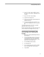
Page 33: ...record for future reference During normal Recirculation the printer prints date time purity and temperature readings once every minute Connecting and Starting the Printer 1 Make sure the printer and...

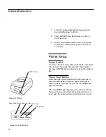
Page 34: ...A The green POWER light will illuminate when the printer is ON Paper Feed Button Press this button once to advance the tape one line or hold the button down to advance paper continuously When the pape...

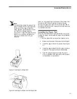
Page 35: ...raight 3 Insert the paper roll into the printer See Figure C 4 Insert the paper straight into the paper slot see Figure D The paper will feed automatically 5 Tear off a strip of paper and close the co...

Page 36: ...ended handling procedure This may be done in an ultrasonic cleaner or with a soft brush 6 Thoroughly rinse the cell in deionized or distilled water following the detergent or acid cleaning 7 After cle...

Page 37: ...n port Close door 11 Press the UP or DOWN arrow to select YES and then press ENTER Display will now read Reconnected Water NO 12 Attach feed water supply removed in step 4 13 Press the UP or DOWN arro...

Page 38: ...d be done prior to removing a cartridge pack The unit needs to be plugged in and operating to correctly perform this depressurization step 1 IMPORTANT Disconnect inlet water from the left back of unit...

Page 39: ...plete sanitization 1 Remove the feed water line by depressing the stainless steel thumb pad 2 Depressurize the system by opening the remote dispenser or from an operational unit in the normal recircul...

Page 40: ...insert it into the dispense arm mani fold Gently turn it clockwise until it is fully seat ed Remove the protective cap from the filter bell 3 Rinse 1 2 liters of water through the filter to drain pri...

Page 41: ...ame type and rating See Replacement Parts 4 Replace fuse drawer 5 Reattach the power cord 6 Operate normally Shutdown If the NANOpure DIamond Analytical is to be shut down for an extended period of ti...

Page 42: ...eed water line pressure switch plug or pressure switch cord to the or jumper plug not connected to receptacle located on the upper left pump interlock hand section of the NANOpure DIamond Insufficient...

Page 43: ...I S T module perform the calibration function WITHOUT the calibration module as if you had it answer YES to prompt The display will read Calibration failed but this will clear any incorrect offset to...

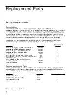
Page 44: ...presentative for additional information on the expendables kit Recommended Description Catalog No Quantity DIamond Kit Organic Free R O Distilled Feed D50280 1 DIamond Kit Organic Free Deionized Feed...

Page 45: ...1190X1 1 Pressure Regulator 1 Resistivity Cell E896X4 1 Power Supply PC Board TNX116 1 Calibration PC Board PC1190X2 Resistivity Meter PC Board PC896X2 1 Check Valve PMX214 1 Flow Sensor ME1190X1 Flus...

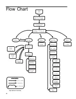
Page 46: ...rmolyne Vx xx Style English Advanced menu Set Time Set Date Optional Printer Date Format Set Cell Constant Adjust Set Point Set Display Brightness Diagnostics menu Air Purge Purity display up or down...

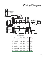
Page 47: ...W1190X1 SW1190X1 SW1190X1 TNX116 TNX116 TNX116 PU1190X1 PU1190X1 PU1190X1 PC896X2 PC896X2 PC896X2 PC1190X2 PC1190X2 PC1190X2 PC1190X1 PC1190X1 PC1190X1 LMX13 ME1190X1 ME1190X1 ME1190X1 WH9 CAL METER H...

Page 48: ...molyne dealer from whom you purchased this unit or can be obtained promptly from the factory When service or replacement parts are needed we ask that you check first with your dealer If the dealer can...

Page 49: ...own discretion Heating elements however because of their susceptibility to overheating and contamination must be returned to our factory and if upon inspection it is concluded that failure is not due...

Page 50: ...50...

Page 51: ...51...

Page 52: ...9001 ISO REGISTERED Barnstead Thermolyne 2555 Kerper Blvd P O Box 797 Dubuque IA 52004 2241 Phone 319 556 2241 800 553 0039 Fax 319 589 0516 E Mail Address mkt barnstead com...

Reviews: