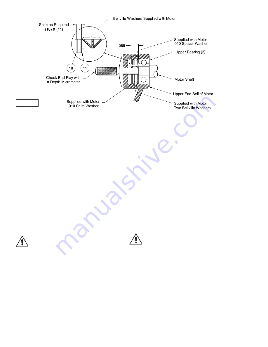
background image

10

FIGURE 3

Vertically lift the outside motor housing (1) from bearing 
bracket (4) with lifting strap (24). Inspect square ring (3) for 
damage or cuts. Remove the upper motor bolts and lift upper 
end bell from motor (47). Examine upper bearing (2) and 
replace if required. If replacement is required, remove bearing 
(2) from motor shaft using a wheel puller. 

NOTE SPECIAL BELLVILLE WASHERS

 in upper motor 

housing required to compensate for shaft expansion. These 
Bellville washers and spacer shims (10) and (11) must be 
properly reinstalled to give the required constant down force 
on the motor shaft. See Section F-3.3.

Vertically lift stator. Inspect winding for shorts and resistance. 
To test the temperature sensor (if equipped), check for continu-
ity between the black and white wires. If found to be defective 
contact a motor service station or Crane Pumps & Systems 
service department. Pull motor rotor and lower bearing (5) 
vertically from bearing bracket (4). Examine bearing (5) and 
replace if required. If replacement is required, remove bear-
ing (5) from motor shaft using a wheel puller. Check rotor for 
wear. If rotor or the stator windings are defective, the complete 
motor must be replaced. While disassembled, check moisture 
sensor wires (31), that they are secured to electrodes (29) with 
lockwashers (34) and screws (33).

Important ! 
All parts must be clean before reassembly

.

F-3.2) Reassembly:
Bearings -

 When replacing bearings, be careful not to 

damage the rotor or shaft threads. (If so equipped, fi ll notch 
should face the rotor core for both upper and lower bearings). 
Clean the shaft thoroughly. Apply adhesive compound (42) to 
the shaft and press bearing (5) on the motor shaft, position 
squarely onto the shaft applying force to the inner race of the 
bearing only, until bearing seats against shoulder of the shaft. 
Reassemble top bearing (2) in the same manner.

Motor -

 Slide lower bearing (5) and motor rotor squarely into 

the bearing bracket (4) until bearing seats on the bottom. 
Position motor housing and stator into pilot, install bellville 
washers and shims (10) and (11) in upper end bell. 

Position upper motor end bell aligning holes and thread cap 
screws into bearing bracket (4). Torque to 16 ft. lb.. Place all 
motor leads above the motor. Position square ring (3) over 
bearing bracket (4) and lower housing (1) over motor and into 
pilot, being sure to orient motor housing handle parallel to mo-
tor end bell reliefs. Apply thread locking compound (38) to cap 
screws (6) threads and install with nut (7).Torque to 24 ft. lb.

F-3.3) Checking Of End-Play:

Measure distance with micrometer from the top surface of the 
motor cover to the end of the shaft. See Figure 3. Temporar-
ily set the partially assembled unit on the lower end of the 
shaft, causing the bearings to slide up in the bearing retainer. 
When the bearings bottom securely, again measure the 
distance from the top surface of the motor cover to the end 
of the shaft. This difference should be between .015 to .030 
inches. If the end-play is within these tolerances, proceed 
with reassembly. If the end-play is not within the above listed 
tolerances, the motor upper end bell must be disassembled 
and suffi cient .010 shims (10) must be added or removed as 
required. Reassemble and recheck again for the required 
listed end-play tolerance.

F-4) Shaft Seal and Diaphragm Service:

Important! - Handle seal parts with extreme care. 
do not scratch or mar lapped surfaces.

F-4.1) Disassembly and Inspection:
Diaphragm -

 To examine or replace the diaphragm (14) or 

shaft seal (12), remove impeller (48) as outlined in paragraph 
F-2.1. Drain oil from seal chamber as outlined in paragraph 
F-1.3. Remove cap screws (25) and lifting strap (24). Set unit 
upside down on blocks to avoid damaging cords. Remove 
socket head cap screws (17) and lift seal plate (13) vertically,
being cautious to avoid seal damage, together with diaphragm 
(14), clamp (15) and outboard stationary member (12A) of 
shaft seal (12), from bearing bracket (4). Examine diaphragm 
(14), if it is ruptured, cracked or damaged, replace by removing 
screws (16) and diaphragm clamp (15), Also, clean out vent 
holes in seal plate (13). Check moisture sensor probes (29) 
for damage. Replace by disconnecting wires (31) by removing 
screws (33) and lockwashers (34). Then remove probe (29) 
from bearing bracket (4).

Summary of Contents for BARNES 4DSE-L Series

Page 1: ...he right to change product without prior written noti cation 420 Third Street 83 West Drive Bramton Piqua Ohio 45356 Ontario Canada L6T 2J6 Phone 937 778 8947 Phone 905 457 6223 Fax 937 773 7157 Fax 9...

Page 2: ...8 20 CROSS SECTION Fig 13 21 EXPLODED VIEW Fig 114 15 22 23 PARTS LIST 24 25 RETURNED GOODS POLICY 26 WARRANT START UP REPORT WARRANTY REGISTRATION SPECIAL TOOLS AND EQUIPMENT INSULATION TESTER MEGGER...

Page 3: ...insert ngers in pump with power connected Always wear eye protection when working on pumps Make sure lifting handles are securely fastened each time before lifting DO NOT operate pump without safety d...

Page 4: ...Hardware 300 series stainless steel CORD ENTRY 40 Ft 12 1m Cord Epoxy sealed housing with secondary pressure grommet for sealing and strain relief SPEED 1150 1750 RPM 60Hz nominal UPPER BEARING Desig...

Page 5: ...300 series stainless steel CORD ENTRY 40 Ft 12 1m Cord Epoxy sealed housing with secondary pressure grommet for sealing and strain relief SPEED 1150 1750RPM 60Hz nominal UPPER BEARING Design Single Ro...

Page 6: ...g should be as short as possible Both a check valve and a shut off valve are recommended for each pump being used The check valve is used to prevent back ow into the sump Excessive back ow can cause o...

Page 7: ...575 3 1150 E 5 4 34 4 10 4 SOW 0 75 4DSE7596L 7 5 200 230 3 1150 B D 24 4 21 3 107 8 124 10 4 SOW 0 75 0 75 4DSE7546L 7 5 460 3 1150 D 10 6 62 0 10 4 SOW 0 75 2 99 4DSE7556L 7 5 575 3 1150 D 8 48 49 6...

Page 8: ...t a preventive mainte nance program is recommended and suggested to include the following checks 1 Inspect motor and seal chambers for oil level and contamination and repair as required per section F...

Page 9: ...ler 48 or replace wear ring 60 on High Ef ciency pumps disconnect power remove hex nuts 7 and vertically lift motor and seal assembly from body 43 Clean out body if necessary Clean and ex amine impell...

Page 10: ...ille washers and shims 10 and 11 in upper end bell Position upper motor end bell aligning holes and thread cap screws into bearing bracket 4 Torque to 16 ft lb Place all motor leads above the motor Po...

Page 11: ...ce facing bearing bracket 4 slide rotating member 12D onto shaft using seal pusher until lapped faces of 12D and 12E are together See Figure 6 It is extremely important to keep seal faces clean during...

Page 12: ...s outlined in paragraph F 2 1 Then remove screws 52 and adapter 53 Reassemble by placing gasket 54 and adapter 53 on volute 43 with screws 52 Reassemble volute onto pump assembly as outlined in paragr...

Page 13: ...uired 7 Shipping instructions 8 Billing Instructions G 2 PART NUMBER The part number consists of a six 6 digit number which ap pears in the catalog A one or two letter suf x may follow this number to...

Page 14: ...impeller for freedom of operation security and condition Clean impeller and inlet of any obstruction 9 Loosen union slightly to allow trapped air to escape Verify that turn off level of switch is set...

Page 15: ...15 FIGURE 10 4DSE L Pump Series...

Page 16: ...16 FIGURE 11 4DSE L Pump Series...

Page 17: ...17 4DSE L Pump Series FIGURE 12...

Page 18: ...1 036852 Gasket Rubber 20 6 033824 Stud 3 8 16 x 2 00 21 1 051937 Square Ring Buna N 22 5 016405 Splice Cap All Except 5Hp 1Ph 7 5Hp 200V 3Ph 030148 Splice Cap For 5Hp 1Ph 7 5Hp 200V 3Ph 23 4 1 529 1...

Page 19: ...9 00 Dia 084894TQ 8 88 Dia 084894TR 8 75 Dia 5HP STD 084894TS 8 62 Dia 084894TT 8 50 Dia 084894TU 8 38 Dia 084894TV 8 25 Dia 084894TW 8 12 Dia 084894TX 8 00 Dia 084894TY 7 88 Dia 084894TZ 7 75 Dia 08...

Page 20: ...met For 4DSE5024L ONLY 49E 1 Control Cable Not Sold Separately 49F 1 051448 Gland Nut 49G 1 021531 Friction Ring 49H 1 066871 Grommet 49J 1 030169 Ground Screw 10 32 x 625 Lg Stainless 52 8 24 113 1 F...

Page 21: ...21 4DSE HL High Ef ciency Pump Series FIGURE 13...

Page 22: ...22 4DSE HL High Ef ciency Pump Series FIGURE 14...

Page 23: ...23 4DSE HL High Ef ciency Pump Series FIGURE 15...

Page 24: ...ainless 19 1 036852 Gasket Rubber 20 6 033824 Stud 3 8 16 x 2 00 21 1 051937 Square Ring Buna N 22 5 016405 Splice Cap All Except 5Hp 1Ph 10Hp 030148 Splice Cap For 5Hp 1Ph 10Hp 23 4 1 529 1 Hex Hd Sc...

Page 25: ...5Ft 072700XL 100Ft 072700XP 125Ft 072700XS 150Ft 072700XV 175Ft 072700XY 200Ft 49A 1 Power Cable Not Sold Separately 49B 1 051447 Gland Nut 1 072559 Gland Nut For 4DSE5024HL 10HP 49C 2 051450 Friction...

Page 26: ...o Insure That Employees Will Not Be Exposed To Health Hazards In Handling Said Material All Applicable Laws And Regulations Shall Apply IMPORTANT WARRANTY REGISTRATION Your product is covered by the e...

Page 27: ...27 NOTE...

Page 28: ...guarantees in the nature of performance speci cations furnished in addition to the foregoing material and workmanship warranties on a product manufactured by us if any are subject to laboratory tests...

Page 29: ...m Does impeller turn freely by hand Yes No Condition of equipment Good Fair Poor Condition of cable jacket Good Fair Poor Resistance of cable jacket Good Fair Poor Resistance of cable and pump motor m...

Page 30: ...ction Pump Off L1 L2 L2 L3 L3 L1 Voltage supply at panel line connection Pump On L1 L2 L2 L3 L3 L1 Amperage Load connection Pump On L1 L2 L3 FINAL CHECK Is pump seated on discharge properly Check for...

Page 31: ...CITY STATE ZIP MODEL NO SERIAL NO PART NO BRAND IMPORTANT WARRANTY REGISTRATION Your product is covered by the enclosed Warranty Complete the Warranty Registration Form and return to Crane Pumps Syst...

Page 32: ...CRANE PUMPS SYSTEMS INC WARRANTY SERVICE GROUP 420 THIRD STREET PIQUA OHIO 45356 U S A FOLD HERE AND TAPE DO NOT STAPLE PLACE STAMP HERE...

Reviews: