background image

28

1. Use the DOWN arrow key to increment the time period desired.

2. Press the MENU key to enter your selection.

Recorder Output

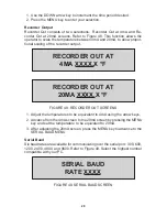
Recorder Out consists of two selections:  Recorder Out at 4mA and Re-
corder Out at 20mA screens. Refer to Figure 48. This function allows the
operator to scale the temperature between 4mA and 20mA, to allow propor-
tional scaling of the recorder output.

RECORDER OUT AT

4MA XXXX.X °F

RECORDER OUT AT

20MA XXXX.X °F

FIGURE 48. RECORDER OUT SCREENS

1. Adjust the temperatures to be equivalent to 4mA using the arrow keys.

2. Advance from the 4mA screen to the 20mA screen by pressing the MENU

key and set the temperature to be equivalent to 20mA.

3. After adjusting the 20mA screen, press the MENU key to advance to the

SERIAL BAUD MENU.

Serial Baud

Six baud rates are available for communicating over the serial port:  300, 600,
1200, 2400, 4800, and 9600. Refer to Figure 49. Select the highest number
compatible with your PC.

SERIAL BAUD

RATE XXXX

FIGURE 49. SERIAL BAUD SCREEN

Summary of Contents for 689-0010

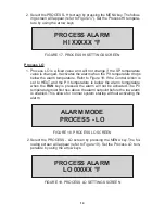
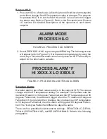
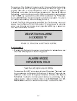
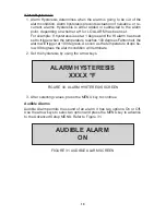
Page 1: ...TROLLER R S ADVANCED MODEL 689 0010 689 0015 Barnant Company 28W092 Commercial Avenue Barrington Illinois U S A 60010 2392 847 381 7050 847 381 7053 Fax 800 637 3739 www barnant com e mail barnant bar...

Page 2: ...irectives Specifications Report Number 73 23 EEC EN61010 1 A2 1995 TR9755 93 68 EEC EN61010 2 010 1995 89 336 EEC EN61326 1 A1 1998 TR9756 92 31 EEC 93 68 EEC The last two digits of the year in which...

Page 3: ...ED Annunciators 5 How To Use This Product 6 INSTALLATION 7 INITIAL HARDWARE SETUP 7 SETUP PROCEDURE 9 Sensor Types 9 Thermocouple 10 Thermistor 10 Platinum RTD 10 Temperature Scale 11 Alarm Selections...

Page 4: ...ent Definition 26 Control Parameters CP 27 Cycle Time 27 Run Time 27 Recorder Output 28 Serial Baud 28 Power Up Control 28 OPERATION 30 CONTROL MODE 30 RAMP AND SOAK MODE 31 TROUBLESHOOTING AND MAINTE...

Page 5: ...move power cord from wall socket before checking or replacing a fuse High voltages exist on fuse terminals WARNING To avoid electric shock the power cord protective grounding conductor must be connect...

Page 6: ...Controller R S advanced model Refer to Figure 1 for a view of the front panel of the Temperature Controller R S Refer to Figures 2 and 3 for a view of the back panels of the 115 V or 230 V versions F...

Page 7: ...re control and may be unsafe Because of the many system vari ables optimum heater sizing must be determined experimentally however an approximation can be made through a few calculations These calcula...

Page 8: ...a computer An IBM compatible PC personal computer disk is included with the R S controller along with a separate operator s manual It can be used to set up the controller and perform logging and other...

Page 9: ...trol alarm con ditions and silence the audible alarm Pressing the ALARM key will erase any alarm messages on the display and stop the ALARM from flashing If the alarm condition is still present the AL...

Page 10: ...rear panel Connect a serial cable between the Controller RS232 connector and a PC and follow the instructions for setup in the separate PC program op erator manual 2 Setup the operating parameters Pre...

Page 11: ...rature limit con trol protection system where a fault condition could result in fire or other hazard Failure to install such a system could result in injury to personnel or damage to property 3 Plug t...

Page 12: ...er maximum of 15 A to the unit 6 Install the PC personal computer cable to the RS 232 C serial commu nications terminal if desired Refer to your PC hardware guide for PC connections 7 The following ch...

Page 13: ...The setup mode can only be entered when the Temperature Controller is stopped 1 Set the ON OFF switch on the rear panel to ON The LEDs will light and all segments will light temporarily as a check of...

Page 14: ...S R and N 3 Select the thermocouple type by pressing the MENU key To ensure proper operation be sure that the correct thermocouple type is con nected at the thermocouple jack before running the progr...

Page 15: ...ey to advance to Temperature Scale selection 100 OHM RTD ALPHA 003850 FIGURE 10 PLATINUM RTD SELECTION SCREEN Temperature Scale 1 After pressing the MENU key in the SENSOR TYPE screen the program will...

Page 16: ...ct AUTO RESET the relay will automatically shut off when the PV temperature falls out of the alarm setpoint temperature For MANUAL RESET the alarm relay is turned off when the ALARM key is pressed The...

Page 17: ...s Celsius and the SP setpoint temperature is set at 55 degrees Celsius the alarm will trigger at 60 degrees If the opera tor resets the SP temperature to 57 degrees then the process alarm value will s...

Page 18: ...re Refer to Figure 18 If the Control Action is set to HEAT and the PV temperature is below the alarm temperature when the RUN key is pressed the alarm will not be activated The PV temperature must fir...

Page 19: ...ue is set press the LEFT arrow key to adjust for the other alarm variable PROCESS ALARM F HI XXXX X LO XXXX X FIGURE 21 PROCESS HILO SETTINGS SCREEN Deviation Alarms Deviation alarms are offset values...

Page 20: ...s when the RUN key is pressed the alarm will not be activated The PV temperature must first rise above the alarm setpoint before the alarm is enabled This allows for normal system startup without acti...

Page 21: ...ing screen will appear refer to Figure 25 Set the Deviation HI temperatures by using the arrow keys Once the alarm value is set press the MENU key to advance to one of the other alarm variables Deviat...

Page 22: ...Figure 28 ALARM MODE DEVIATION BAND FIGURE 28 DEVIATION BAND SCREEN For example if the SP temperature is set for 50 degrees and the Devia tion BAND is set for 25 degrees the alarm will trigger at 25 d...

Page 23: ...temperature reaches 100 degrees Fahrenheit the alarm will trigger at 100 degrees As soon as the temperature drops be low 99 degrees the alarm condition will terminate 2 Set the hysteresis by using the...

Page 24: ...more accurate reading Refer to Figure 33 Calibration offset and PV actual temperatures are displayed SENSOR OFFSET CAL XX X XXX X F FIGURE 33 SENSOR CALIBRATE SCREEN 2 To adjust the values in this op...

Page 25: ...ty feature is designed to stop the Temperature Controller if the heater output is on for the amount of time set in Loop Break Stop and the PV temperature does not increase more than 1 0 F If the COOL...

Page 26: ...OL MODE PID FIGURE 37 CONTROL SCREEN CONTROL ACTION HEAT FIGURE 36 CONTROL ACTION SCREEN 2 The default setting is HEAT Use the DOWN arrow key to select either heat or cool actions Press the MENU key t...

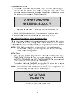
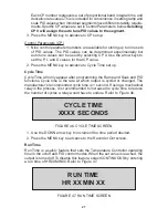
Page 27: ...ve stability in the system It should be used when system stability or accuracy requirements are too great for use of on off control NOTE PID Settings should not be changed from the manufacturers AUTO...

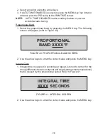
Page 28: ...ollowing screen will appear refer to Figure 40 PROPORTIONAL BAND XXXX F FIGURE 40 PROPORTIONAL BAND SCREEN 2 Use the arrow keys to enter the correct value and press the MENU key Integral Time 1 Integr...

Page 29: ...f automatically increasing or decreasing setpoint temperatures within specific time periods using an operator pre set program By setting the values on the segment screens an operator can tell the tem...

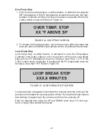
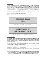
Page 30: ...AK SCREEN SEG XX 0000 F HR XX MIN XX CP X FIGURE 45 PROFILE ALTERATION SCREEN Segment Definition The segment temperature displayed indicates the desired temperature at the end of the segment time The...

Page 31: ...nce to Cycle Time set up Cycle Time Cycle Time will only appear after programming the Ramp and Soak and PID functions Cycle time is the rate at which output is cycled or changed The manufacturer s rec...

Page 32: ...4MA XXXX X F RECORDER OUT AT 20MA XXXX X F FIGURE 48 RECORDER OUT SCREENS 1 Adjust the temperatures to be equivalent to 4mA using the arrow keys 2 Advance from the 4mA screen to the 20mA screen by pr...

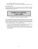
Page 33: ...ed primarily to function in the event of a power failure If a power outage occurs Last State will start the process from where it last ended when the power went out Stopped will leave the process off...

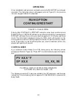
Page 34: ...Soak mode The information displayed during the RUN mode will depend on the setup options selected General display functions for each mode are shown below Depending on the ALARM options set alarm cond...

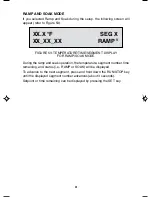
Page 35: ...TURE TIME SEGMENT DISPLAY FOR RAMP SOAK MODE During the ramp and soak operation the temperature segment number time remaining and status i e RAMP or SOAK will be displayed To advance to the next segme...

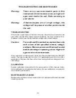
Page 36: ...ontinued fire protection replace fuse only with a fuse of the specified current voltage and type Remove power cord from wall socket before checking or replacing a fuse High volt ages exist on fuse ter...

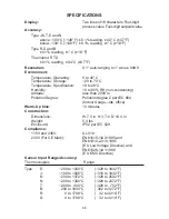
Page 37: ...on condensing Altitude less than 2000 m Pollution Degree Pollution degree 2 per IEC 664 Indoor Usage lab office Warm Up time 10 minutes Construction Dimensions W 7 3 in H 3 7 in D 10 0 in Weight 5 3 l...

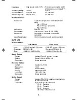
Page 38: ...e Probe Input Connector Mini ANSI flat blade thermocouple jack Calibration ITS 90 NIST monograph 175 Lead resistance 500 ohm max Common mode voltage 5 V max Thermistor Probe Input Any of the YSI serie...

Page 39: ...ach lead balanced OUTPUTS AC Line Output 115V Model 230V Model Input 115V AC typical 15A max 230V AC typical 15A max Connector NEMA 5 15R Reverse IEC 320 C20 Fuse 15A 230V 3AG Slo Blo 15A 230V 3AG Slo...

Page 40: ...The warranty period for this product is noted on the Warranty Card PRODUCT RETURN To limit charges and delays contact the seller or manufacturer for authoriza tion and shipping instructions before re...

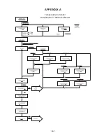
Page 41: ...A 1 APPENDIX A Temperature Controller Setup Mode for Advanced Model...

Page 42: ...A 2 Temperature Controller Setup Mode for Advanced Model...

Page 43: ...r settable time period Adjust Loop Break Stop in user setup normal OPEN PROBE STOP Detected open probe sensor while running Check probe normal OVER PROBE STOP PV exceeded the upper limit of selected p...

Page 44: ...nel Mount Kit 689 0098 All models Heater Sizing Software 689 0097 All models Alarm Recorder Output Connector 689 0078 230V only Input Cord IEC320 NEMA 6 15P 689 0079 230V only Input Cord IEC320 CONT E...

Reviews: