03
Recommendations, Warnings & Installation
Receiving inspection
Upon receiving the pump, it should
be inspected for damage or
shortages. If damage has occurred,
file a claim immediately with the
company that delivered the pump. If
the manual is removed from the
packaging, do not lose or misplace.
Storage
Any product that is stored for a
period longer than six (6) months
from the date of purchase should be
bench tested prior to installation. A
bench test consists of, checking the
impeller to assure it is free turning
and a run test to assure the motor
(and switch if provided) operate
properly. Do not pump out of liquid.
Controls
Be sure the electrical specification of
the control selected properly match
the electrical specifications of the
pump.
Installation
Location
- The pump should be
located as near as possible to the
liquid to be pumped and in no case
should the pump be more than 25
feet above the surface of the liquid
supply. The pump should always be
as level as possible.
Allow a minimum of 18 inches in
front of the pump case cover or
hatch cover to permit easy removal
and access to the interior of the
pump. On belt driven units, allow a
minimum of 10 inches at the shaft
end to permit easy removal of the
pedestal or rotating cartridge.
Locate the pump on a firm footing to
make sure the pump will not move
due to vibration. Flex coupled and V-
belt driven units should be
permanently grouted onto a cement
foundation. The pumps should be
level to provide favorable operating
conditions. In addition, the flexible
coupling should be realigned after
grouting in order to eliminate
excessive wear on the coupling.
The use of pipe the same size as the
port size is highly recommended.
Using a smaller pipe line can cause
internal damage. Make sure all lines
have air-tight joints. The smallest air
leak in the suction line may prevent
the pump from priming. All
horizontal suction lines should slope
up to the pump to avoid trapped air
pockets. All piping should be
properly supported.
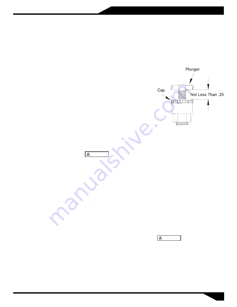
The plunger and handle should be
no less than 1/4" above the cap
which indicates the seal chamber is
full or pressurized. If less than 1/4"
above cap, the seal chamber needs
additional lubricant.
Priming
Remove pipe plug in top of body and
fill the pump body completely with
solids free liquid. In freezing weather
prime pump with warm water.
barmesapumps.com
Motor connection
All wiring of motor and control,
overload protection and grounding
should be in accordance with the
National Electrical Code, State and
Local codes. Make motor connection
per label located on motor or motor
manufactures manual.
All units rotate clockwise as viewed
from shaft end of pump. It is
necessary to slide one half of the flex
coupling back when checking
rotation to eliminate the possibility
of unscrewing the impellers which
are threaded on the shaft.
Rotation
THIS PUMP SHOULD
N OT B E O P E R AT E D W I T H O U T A
S T R A I N E R O N T H E E N D O F T H E
SUCTION LINE TO PREVENT STICKS,
STONES, RAGS AND OTHER FOREIGN
MATTER FROM BEING DRAWN INTO THE
IMPELLER. THE STRAINER SHOULD BE
CLEANED REGULARLY TO INSURE FULL
FLOW.
CAUTION
Suction
Connect discharge hose or pipe to
the discharge port. Make sure all
lines have air-tight joints
Discharge
Lubrication
The seal is the only component that
requires lubrication. It is grease filled
at the factory but must be checked
before putting unit into operation. A
spring loaded grease cup attached to
the seal chamber maintains the
grease fill.
Filling through the grease cup by
turning the handle clockwise in order
to compress the plunger spring into
the cap. Removing cap, fill with grease,
replace cap and release spring by
turning handle counterclockwise until
it is in contact with plunger flange.
Approved grease: SHELL ALVANIA R2,
MOBILE MOBILUX 2, AMPOL RR2, B.P.
ENERGERASE LS2, CALTEX MULTIFAX 2
or equal.
PLUNGER AND HANDLE
MUST BE TOGETHER AND NO LESS
THAN 1/4" ABOVE CAP DURING PUMP
OPERATION.
CAUTION


