background image

AIRFLOW & DEFROST

Cut-In/Cut-Out

Cut-In 

Temp (

o

F)

Cut-Out 

Temp (

o

F)

Pans

33

29

Top Coil

36

31

AIRFLOW & PRODUCT LOAD

Hillphoenix cases provide maximum product capacity within the 
refrigerated air envelope.  Please keep products within the ap-
propriate load limit.

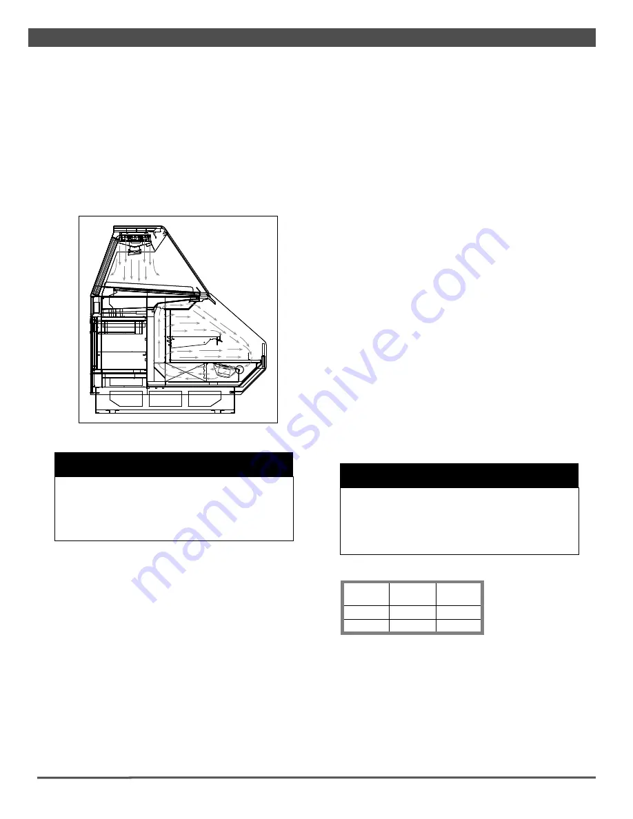
It is important that you do not overload the food product display 
so  that  it 

impinges  on  the  airfl ow  pattern  (Fig.  11).  Overload-

ing will cause malfunction and the loss of proper temperature 
levels, particularly when discharge and return air sections are 
covered.


W A R N I N G

Always keep product within the designated air 
curtain.  Failure to do so may result in case 
malfunction and product losing proper tempera-
ture, resulting in sub-standard operation and 
increased chances of food contamination.


PTD-RGC cases are available with the defrost and temperature 
controls mounted at the case or initiated by the rack controller.

When the controls are mounted at the case, the single time-off 
defrost is initiated by the Dixell XR70CX controller mounted in 
the slide out control box. During defrost, all valves close and 
the pump cycles OFF. When in refrigeration mode, the glycol 
fl ow to the top coil, shelves and the Coolgenix pans is inde-
pendently controlled by the Dixell controller. If none of these 
components requires fl ow, all solenoids close (including DX 
liquid-line valve) and the pump is cycled OFF.

When defrost and temperature are controlled from the rack, 
the time-off defrost is controlled by a set of normally open con-
tacts at the rack controller. When in refrigeration mode, the 
top coils, shelf  and the Coolgenix pans are controlled as three 
independent, temperature-controlled cases. Again, if none of 


C A U T I O N

If the shelves are removed from the case or other-
wise not utilized, the shelf setpoint (SAA) must be 
raised  to 90 

o

F  to prevent the pump from running 

when only the shelves are calling for refrigeration.  
Failure to do so could result in early pump failure.


these components requires fl ow, all valves close and the pump 
cycles OFF.

Whether the controls are managed at the case or by the rack 
controller, the case and product temperatures are maintained 
by having the top coils, shelves and the Coolgenix deck pans 
cycle through their individual DIFFERENTIAL range.  If the 
Dixell XR70CX Controller is used, the fl ow of the chilled fl uid to 
the Coolgenix pans, shelves and top coil circuit is controlled by 
comparing the temperature readings of the appropriate tem-
perature sensor against either the CUT-IN or CUT-OUT setpoint 
to the DIFFERENTIAL control settings.  To determine CUT-OUT 
temperature, calculate the CUT-IN minus the DIFFERENTIAL.  
To determine CUT-IN temperature, calculate the CUT-OUT plus 
the DIFFERENTIAL.  For example, the factory setting for pan 
CUT-OUT is 29°F with a 4°F DIFFERENTIAL which yields a CUT-
IN setting of 33°F. 
The factory settings should be considered a guide and may 
need to be adjusted based on store conditions.  Because 
these cases are often installed in stores near a meat prepara-
tion area where standard ASHRAE conditions may not apply, 
different settings may be required for optimal operation. 
It is important to consult the guidelines and control setting 
shown on page 2 before setting defrost times.  Further adjust-
ment may be required depending on store conditions.

If your case is equipped with a Dixell temperature and humidity 
controller, see Appendices B1-B4 for operating instructions.

If  you  need  to  convert  pressure  to  temperature  see  Appendix 
C1 for the Sporlan Temperature-Pressure Chart. 

DEFROST & TEMPERATURE CONTROLS

Cases are equipped with either Hot Gas or Timed-Off defrost at 
the owner's option.  

The  hot  gas  defrost  termination  sensor  bulb  and  probe  are 
attached to the dump line which is in the front, left-hand side 
of the case.  

Fig. 11 Airflow pattern

16

Summary of Contents for PTD-RGC

Page 1: ...t 16 Case Cleaning 17 24 Parts Ordering 25 Appendices Table of Contents To ensure proper functionality and optimum performance it is STRONGLY recommended that Hillphoenix specialty cases be installed serviced by qualified technicians who have experience working with commercial refrigerated display merchandisers and storage cabinets For a list of Hillphoenix authorized installation service contracto...

Page 2: ...ii ...

Page 3: ...ith shelf lighting systems for direct or indirect exposure to water or other liquids The use of a misting system or water hose on a display case with a shelf lighting system resulting in the direct or indirect exposure of the lighting system to water can lead to a number of serious issues including without limitation electrical failures fire electric shock and mold in turn resulting in personal inj...

Page 4: ...x installation and operations handbooks accompanied by an alert symbol paired with the word DANGER WARNING or CAUTION All warning messages will inform you of the potential hazard how to reduce the risk of case damage personal injury or death and what may happen if the in structions are not properly followed W A R N I N G Indicates a potential threat of death or serious injury if all instructions a...

Page 5: ...Revision History new manual format_12 13 energy data_01 14 energy data_03 14 endviews_09 14 support diagram and parts page_02 15 warranty_04 16 energy data_09 16 v ...

Page 6: ...Volts 120 Volts Amps Watts Amps Watts Amps Watts Amps Watts Amps Watts PTD RGC BASE 6 2 0 6 72 1 8 3 0 9 108 10 4 1 2 144 12 4 1 2 144 Defrost Controls Model Defrosts per Day Run Off Time min Electric Defrost Timed Off Defrost Hot Gas Defrost Fail Safe min Termination Temp o F Fail Safe min Termination Temp o F Fail Safe min Termination Temp o F PTD RGC BASE DX 4 65 6 36 42 RRS 4 65 7 36 42 Model ...

Page 7: ...Contained2 Defrost Controls Model Fans per Case High Efficiency Fans Anti Condensate Fans Drain Heaters Optional Defrost Heaters 120 Volts 120 Volts 120 Volts 208 Volts Amps Watts Amps Watts Amps Watts Amps Watts PTD RGC DOME 4 1 6 8 10 12 Model Lights per Row Light Length ft Fluorescent Lighting Per Light Row Clearvoyant LED Lighting Per Light Row Standard Power Cornice or Shelf High Power Cornice...

Page 8: ...ASE 26 in 66 0 cm 96 1 2 in 245 1 cm 8 case 120 1 2 in 306 1 cm 10 case 144 1 2 in 367 0 cm 12 case ELECTRICAL RACEWAY LOWER REAR STORAGE WITH DOORS 6 1 4 in 15 9 cm 42 in 106 7 cm 51 in 129 5 cm 1 1 2 in 3 7 cm 34 5 16 in 87 2 cm 20 3 8 in 51 7 cm 9 1 4 in 23 5 cm 13 7 8 in 35 2 cm 22 3 4 in 57 8 cm 14 in 35 6 cm LOAD LIMIT LINE 16 3 4 in 42 5 cm 14 5 8 in 37 2 cm REFLECTIVE REAR LOAD DOORS 16 13...

Page 9: ...l or the express receipt and 2 signed by the carrier s agent otherwise the carrier may refuse the claim If damage becomes apparent after the equipment is unpacked retain all packing materials and submit a written request to the carrier for inspection within 14 days of receipt of the equipment Failure to follow this procedure will result in refusal by the carrier to honor any claims with a conseque...

Page 10: ...neered for air conditioned stores with a maximum ambient of 75 F and 55 relative humidity When selecting the location for placement of this case avoid the following conditions Excessive Air Movement 1 Doors 2 Air conditioned vents 3 Other air sources Excessive Heat 1 Windows 2 Sun 3 Flood lamps 8 feet or less from the product 4 Other heat sources C A U T I O N Locate the horizontal supports under ...

Page 11: ... remaining cases Be certain to properly level all cases Fig 3 Sealing the end frame WATERSHED END FRAME C A U T I O N Installation of 3rd party materials may result in diminished case performance COOLGENIX PANS Deck Pans 1 The Coolgenix deck pans are the main source of cooling 2 All products placed into the Coolgenix case must be at the appropriate temperature before placing into the case 3 Warm p...

Page 12: ...t be used Loading 1 When loading a case the product should be loaded through the rear load door opening 2 The rear doors should never be removed while merchan dising This is recommended to ensure optimum case operation and to prevent contamination of rear door surfaces 3 The front lift glass should only be lifted when cleaning the inside of the glass C A U T I O N Coolgenix pans are not designed t...

Page 13: ...s when the glycol system needs to be drained flushed and recharged usually due to contami nants being added to the approved propylene glycol Charging and air purging should be performed with the hand valve on the DX side of the chiller closed Field charging the chiller system requires bumping the pump The pump is capable of emptying the reservoir faster than fluid can be poured into it When the syst...

Page 14: ...er tight and sealed with the appropriate PVC or ABS cement Drain lines can be run left or right of the tee with the proper pitch to satisfy local drainage requirements When connecting the PVC to the existing floor drains be sure to provide as much downhill slope as possible and avoid long runs of drain lines Do not install condensate drains in contact with non insulated suction lines in order to pr...

Page 15: ... Coil Return Top Coils Refer to the table for the correct number of coils Supply Header Coolgenix Pan Coolgenix Pan Coolgenix Pan Coolgenix Pan Refer to the table for the correct number of pans Pan Solenoid SV 2 Top Coil Solenoid SV 1 Pan Return Header Hand Valve Hand Valve Coolgenix Shelves Coolgenix Shelves optional optional Shelf Solenoid SV 4 Shelf Return Header CASE CONNECTIONS Case Length Nu...

Page 16: ...m 6 in 15 2 cm 12 in 30 5 cm 1 in 2 5 cm 1 in 2 5 cm 15 x 11 MECHANICAL ACCESS FOR ELECT REFRIG AND DRAIN CONNECTIONS TOEKICK 42 in 106 7 cm TOEKICK L C FRONT OF CASE 72 1 2 in 184 2 cm 6 case 96 1 2 in 245 1 cm 8 case 120 1 2 in 306 1 cm 10 case 144 1 2 in 367 0 cm 12 case 123 2 cm 4 case 48 1 2 in 12 ...

Page 17: ...n serious injury or death Fig 7 T 8 light power cords W A R N I N G Using improper DC power supplies may damage the luminaires resulting in sub standard opera tion and increased chances of safety issues injury W A R N I N G Never replace a 24V DC power supply with a T8 or T5 ballast of any kind Ballasts use alternat ing current AC instead of direct current DC and operate at a much higher voltage t...

Page 18: ... shelf luminaires 1 Place hook into shelf roll form at shelf front and rotate rear of luminaire toward the shelf 2 Depress the rear clip so that luminaire can finish rotation and until clip engages the shelf bracket NON SHELF LUMINAIRES Removing non shelf luminaires 1 Simultaniously squeeze the plastic clips at each end 2 When the hooks are disengaged pull the luminaire free Re installing non shelf...

Page 19: ... toekick see pg 7 Have you removed the shipping blocks from the refrigeration and plumbing lines see pg 10 After powering up the case be certain that all of the steps listed below have been completed to ensure proper case functionality safety and compliance with warranty terms 1 Check all lights to ensure they are all functioning properly 2 Check case temperature and adjust controller as needed Be...

Page 20: ...o 90 o F to prevent the pump from running when only the shelves are calling for refrigeration Failure to do so could result in early pump failure these components requires flow all valves close and the pump cycles OFF Whether the controls are managed at the case or by the rack controller the case and product temperatures are maintained by having the top coils shelves and the Coolgenix deck pans cyc...

Page 21: ...nded rear sill access to the thermostats simply by lifting off the ballast cover from under the rear sill It is important to consult the control setting guidelines shown on pages 2 9 before setting defrost times Further adjustment may be required depending on store conditions DETERMINING SUPERHEAT To identify proper superheat settings complete the following 1 Obtain suction pressure from access po...

Page 22: ...n with a soft damp cloth Avoid using harsh or abrasive cleaners as they may dam age the lights Be certain that the luminaires are complete ly dry before re energizing Clean from top to bottom when cleaning the display case to avoid cross contamination If any potentially harmful cleaners are used be certain to provide a temporary separator e g cardboard plastic wrap etc between those cases that are...

Page 23: ...or rear of the case 2 By disconnecting the hoses by use of the quick connects 3 By turning off the chiller rack supply to the system in the machine room 4 By opening up the rear lower panel and turning off the chiller unit This pertains to semi self contained cases Fans and Pressure Plate 1 Diconnect power to the case and wait for fans to come to a complete stand still 2 To access the underside of...

Page 24: ...ved screws for reas sembly Fig 18 Coil cover removal Fig 19 Coil cover topside Fig 20 Coil cover underside 3 Carefully without bending the sheet metal cover lift from the back end of panel and rest the topside of coil cover on pressure plate handles Fig 19 20 4 Clean as necessary Use a spray bottle filled with an approved mild detergent and warm water This location should be accessed by qualified pe...

Page 25: ... load door removal 2 Use a spray bottle filled with an approved mild detergent and warm water 3 Use a clean disposable cloth approved item to thorough ly clean all areas of the case 4 Wipe down doors with a clean disposable cloth approved item 5 Place the cleaned doors on a clean sanitized surface until they are dry CASE CLEANING 21 ...

Page 26: ... refrigeration off to the case by the above methods put the case in a manual defrost through the Dixell Controller Push the DOWN key for more than 2 seconds and a manual defrost will start on the Dixell Con troller The controller must be turned back on when finished cleaning If your case is equipped by a different type of controller refer to the controller manual for putting the case into manual de...

Page 27: ... rear doors and tracks if applicable Remove the rear doors from the tracks Use a mild glass cleaner and a clean paper towel or cloth and wipe down the doors Spray the doors with sanitizer and allow them to air dry Spray the door tracks with a mild cleaning solution and wipe them down with a clean cloth or paper towel A bottle brush may be used for cleaning the grooves in the door track When cleani...

Page 28: ...l for cleaning If the case is not equipped with quick disconnects carefully lift the pans and lean against the front of the case until the case tank is cleaned Remove the pan spanner bars and rear pan support bars Spray the Coolgenix deck pans spanner bars and rear pan support bars with a mild cleaning solution and wipe them down with a clean cloth or paper towel DO NOT put the deck pans in the di...

Page 29: ...d wipe it down with a paper towels or a clean cloth Spray the cutting board with sanitizer and allow it to air dry Spray the rear sill with a mild cleaning solution and wipe it down with paper towels or clean cloth Spray the rear sill with sanitizer and allow it to air dry Replace the cutting board 7 Clean the exterior Spray the exterior panels with a mild cleaning solution and wipe them down with...

Page 30: ... case Re install the Coolgenix deck pans spanner bars and rear pan support bars back into the case It is essential to insure the spanner bars are set back in place to prevent the pans from warping If you have Coolgenix deck pans with disconnects reconnect the pan to the quick connect hose Reconnect the sensor to the center pan and insure proper contact The sensor is essential for the case to PROPE...

Page 31: ... product only extra strength or specialty products may not be suitable Glass Plus standard product only extra strength or specialty products may not be suitable Exceed Multi Surface Glass Cleaner from Kay Chemical Company Greensboro NC Warm Water Note equivalent store brand glass cleaning products are normally acceptable substitutes to the brand name products listed above The cleaning cloths named...

Page 32: ... the part is intended Length of the part if applicable Color of part if painted or color of polymer part Whether part is for left or right hand application Quantity Data tag is located on the left end exterior panel or top interior of the case If the parts are to be returned for credit contact the Parts Department Do not send parts without authorization PARTS ORDERING 28 ...

Page 33: ...A1 A4 Wiring Information B1 B4 Dixell Operating Instructions C1 Sporlan Pressure Temperature Chart D1 Parts List APPENDIX ...

Page 34: ...HITE TO LIGHT POWER WIRE INFORMATION WIRE INFORMATION BLACK TO BLOCK 4 A 2 BLACK FAN POWER WHITE TO BLOCK 4 E 2 WHITE FAN POWER WIRE INFORMATION WIRE INFORMATION BLACK TO DOME SOLENOID BLACK POWER WHITE TO DOME SOLENOID WHITE POWER WIRE INFORMATION WIRE INFORMATION BLACK POWER FROM 6 1 WHITE POWER FROM 6 2 WHITE DOME LIGHT WHITE TO 2 K WHITE TO 5 2 BLACK DOME SWITCH GRAY FRONT SWITCH WHITE TO 1 F ...

Page 35: ...TION GREEN TO ISO GREEN TO ISO GROUND BLACK TO BLOCK 2 E 2 BLACK TO LIGHT POWER WHITE TO BLOCK 2 I 2 WHITE TO LIGHT POWER WIRE INFORMATION WIRE INFORMATION BLACK TO BLOCK 3 A 2 BLACK FAN POWER WHITE TO BLOCK 3 E 2 WHITE FAN POWER WIRE INFORMATION WIRE INFORMATION BLACK TO DOME SOLENOID BLACK POWER WHITE TO DOME SOLENOID WHITE POWER WIRE INFORMATION WIRE INFORMATION BLACK POWER FROM 5 1 WHITE POWER...

Page 36: ...T BLUE DRIVER WHITE DRIVER BLACK DOME LIGHT RED DOME LIGHT GRAY TO 5 C GRAY TO 1 E BLUE DRIVER RED DRIVER BLACK DRIVER BLACK DRIVER WHITE DRIVER RED TOP LIGHT RED TOP LIGHT RED SHELF LIGHT RED SHELF LIGHT BLUE DRIVER BLUE SHELF LIGHT BLUE SHELF LIGHT WIRE INFORMATION WIRE INFORMATION WHITE TO 2 H BLACK SWITCH GRAY SWITCH GRAY TO 2 E WHITE TO 1 F BLACK DRIVER WHITE DRIVER BLACK TO 4 A BLACK LIGHT P...

Page 37: ... BLACK SHELF LIGHT RED SHELF LIGHT BLACK DOME LIGHT GRAY SWITCH WHITE POWER FROM 4 E BLACK DRIVER WHITE DRIVER WIRE INFORMATION WIRE INFORMATION BLACK SWITCH BLACK DRIVER WHITE DRIVER WHITE TO 5 I WHITE TO 1 F BLACK TO 5 G GRAY SWITCH GRAY TO 1 E RED TOP LIGHT RED DRIVER RED SHELF LIGHT RED TOP LIGHT RED SHELF LIGHT BLACK TOP LIGHT BLACK TOP LIGHT BLUE DRIVER BLUE SHELF LIGHT BLUE SHELF LIGHT WHIT...

Page 38: ...PORATOR FANS The fan control mode is selected by means of the FnC parameter FnC C_n fans will switch ON and OFF with the compressor and not run during defrost FnC o_n fans will run even if the compressor is off and not run during defrost After defrost there is a timed fan delay allowing for drip time set by means of the Fnd parameter FnC C_Y fans will switch ON and OFF with the compressor and run ...

Page 39: ...pressor is OFF in case of faulty thermostat probe With COF 0 compressor is always active DISPLAY CF Temperature measurement unit C Celsius F Fahrenheit WARNING When the measurement unit is changed the SET point and the values of the parameters Hy LS US Ot ALU and ALL have to be checked and modified if necessary rES Resolution for C in 1 C dE 0 1 C allows decimal point display Lod Instrument displa...

Page 40: ...will stop as soon as the digital input is de activated 8 4 PRESSURE SWITCH i1F PAL If during the interval time set by did parameter the pressure switch has reached the number of activation of the nPS parameter the CA pressure alarm message will be displayed The compressor and the regulation are stopped When the digital input is ON the compressor is always OFF If the nPS activation in the did time ...

Page 41: ...in 15 Pr2 COF Compressor OFF time with faulty probe 0 y 255 min 30 Pr2 CF Temperature measurement unit C y F C Pr2 rES Resolution in integer dE dec point dE Pr1 Lod Probe displayed P1 P2 P1 Pr2 rEd2 X REP display P1 P2 P3 P4 SEt dtr P1 Pr2 dLy Display temperature delay 0 20 0 min 10 sec 0 Pr2 dtr P1 P2 percentage for disply 1 99 50 Pr2 tdF Defrost type EL el heater in hot gas EL Pr1 dFP Probe sele...

Page 42: ...0 29 4 381 8 17 8 3 16 4 51 5 54 3 30 4 388 0 18 7 8 17 0 52 7 55 6 31 4 394 3 19 7 2 17 7 54 0 56 9 32 4 400 7 20 6 7 18 4 55 3 58 3 33 5 407 2 21 6 1 19 1 56 6 59 6 34 6 413 8 22 5 6 19 9 58 0 61 0 35 7 420 4 23 5 0 20 6 59 3 62 4 36 8 427 1 24 4 4 21 3 60 7 63 8 37 9 433 8 25 3 9 22 1 62 1 65 3 39 0 440 7 26 3 3 22 9 63 5 66 7 40 2 447 6 27 2 8 23 7 64 9 68 2 41 4 454 6 28 2 2 24 5 66 4 69 7 42...

Page 43: ...Remote Bottom Deck L End Panel Trim M End Panel N Fixed End Glass O End Toekick P Electrical Raceway Q Outside Back R Lower Rear Storage w Doors S Shelf Standard T Adjustable Shelf Bracket U Insulated Drain Pan V Air Discharge W Coolgenix Bottom Deck X Strut Y Sliding Rear Load Doors Z Gravity Coil D1 PARTS LIST A B E D F G L M C K I H J Z Q P X Y R S T U V W O N ...

Page 44: ...urned within two weeks after startup 5 If the defective part is not returned to the Manufacturer 6 To service maintenance or wear and tear parts such as lights starters and ballasts MODIFICATIONS TO GENERAL WARRANTY The following sets forth certain modifications to the General Warranty for specific products of Manufacturer DISPLAY CASE AND SPECIALTY PRODUCTS CLEARVOYANT LED LIGHTING The warranty p...

Page 45: ...ter directly on fan motors or any electrical connections All lighting receptacles must be dried off prior to insertion and re energizing the lighting circuit Please refer to the Use and Maintenance section of this installation manual BDM0818 703 Franklin Street PO Box 478 Keosauqua IA 52565 Due to our commitment to continuous improvement all specifications are subject to change without notice Hill...

Reviews: