


Version 3.01
| P2 Series User Guide |
25
www.bardac.com
4.11. IP66 Switched Version Integrated Control Switch and Potentiometer Wiring
The P2 is optionally available with an integrated mains disconnect / isolator and front mounted control switch and potentiometer. This
allows the drive to be operated directly from the front control panel, whilst also providing for options such as Hand / Auto or Local /
Remote Control etc.
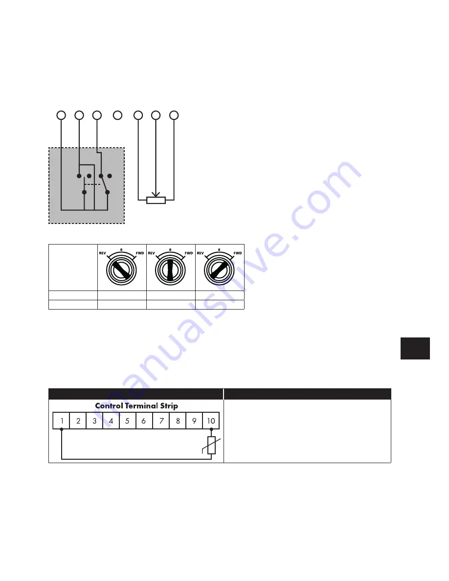
The built in switch and pot are wired inside the terminal cover directly to the user control terminals as shown in the diagram below.
These connections may be disconnected by the user if they are not required.
1 2 3 4 5 6 7
The control switch activates the first two digital inputs as follows:
Switch
Position
DI1
ON
OFF
ON
DI2
ON
ON
OFF
4.12. Motor Thermal Overload Protection
4.12.1. Internal Thermal Overload Protection
The drive has an in-built motor thermal overload function; this is in the form of an “I.t-trP” trip after delivering >100% of the value set in
P-08 for a sustained period of time (e.g. 150% for 60 seconds).
4.12.2. Motor Thermistor Connection
Where a motor thermistor is to be used, it should be connected as follows:
Control Motor Strip
Additional Information
Compatible Thermistor: PTC Type, 2.5kΩ trip level.
Use a setting of P1-13 that has Input 5 function as E-TRIP
“External Trip”, e.g. P1-13 = 6. Refer to section 7.2. Digital
Input Configuration Parameter P1-13 on page 39 for
further details.
Enable the Motor PTC Thermistor Input function in
parameter P2-33.
4
Elec
trical Installation


