background image

Manual 2100-413G
Page

21 of 28

DEFROST CYCLE

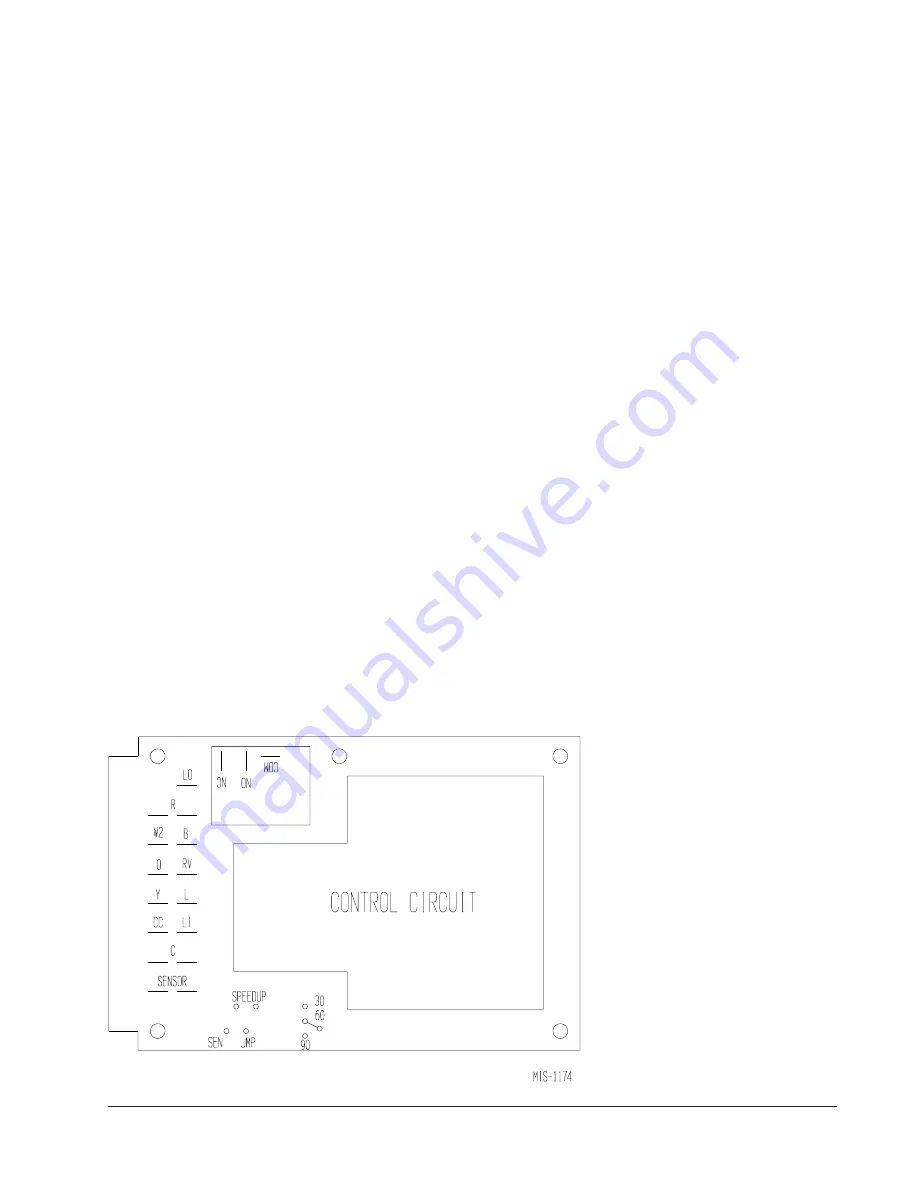
The defrost cycle is controlled by temperature and time
on the solid state heat pump control.  See Figure 12.

When the outdoor temperature is in the lower 40°F
temperature range or colder, the outdoor coil
temperature is 32°F or below.  This coil temperature is
sensed by the coil temperature sensor mounted near the
bottom of the outdoor coil.  Once coil temperature
reaches 30°F or below, the coil temperature sensor
sends a signal to the control logic of the heat pump
control and the defrost timer will start.

After 60 minutes at 30°F or below, the heat pump
control will place the system in the defrost mode.

During the defrost mode, the refrigerant cycle switches
back to the cooling cycle, the outdoor motor stops,
electric heaters are energized, and hot gas passing
through the outdoor coil melts any accumulated frost.
When the temperature rises to approximately 57°F, the
coil temperature sensor will send a signal to the heat
pump control which will return the system to heating
operations automatically.

If some abnormal or temporary condition such as a high
wind causes the heat pump to have a prolonged defrost
cycle, the heat pump control will restore the system to
heating operation automatically after 10 minutes.

The heat pump defrost control board has an option of
30, 60 or 90-minute setting.  All models are shipped
from the factory on the 60-minute pin.  If special
circumstances require a change to another time, remove
the wire from the 60-minute terminal and reconnect to
the desired terminal.  The manufacturer's
recommendation is for 60-minute defrost cycles.  Refer
to Figure 12.

There is a cycle speed up jumper on the control.  This
can be used to reduce the time between defrost cycle
operation without waiting for time to elapse.

Use a small screwdriver or other metallic object, or
another 1/4 inch QC, to short between the 

SPEEDUP

terminals to accelerate the HPC timer and initiate
defrost.

Be careful not to touch any other terminals with the
instrument used to short the 

SPEEDUP

 terminals.  It

may take up to 10 seconds with the 

SPEEDUP

 terminals

shorted for  the speedup to be completed and the defrost
cycle to start.

As soon as the defrost cycle kicks in remove the
shorting instrument from the SPEEDUP terminals.

Otherwise the timing will remain accelerated and run
through the 1-minute minimum defrost length sequence
in a matter of seconds and will automatically terminate
the defrost sequence.

There is an initiate defrost jumper (sen jump) on the
control that can be used at any outdoor ambient during
the heating cycle to simulate a 0° coil temperature.  This
can be used to check defrost operation of the unit
without waiting for the outdoor ambient to fall into the
defrost region.

By placing a jumper across the 

SEN JMP

 terminals (a

1/4 inch QC terminal works best) the defrost sensor
mounted on the outdoor coil is shunted out and will
activate the timing circuit.  This permits the defrost
cycle to be checked out in warmer weather conditions
without the outdoor temperature having to fall into the
defrost region.

In order to terminate the defrost test the 

SEN JMP

jumper must be removed.  If left in place too long the
compressor could stop due to the high pressure control
opening because of  high pressure condition created by
operating in the cooling mode with outdoor fan off.

Pressure will rise fairly fast as there is
likely no actual frost on the outdoor
coil in this artificial test condition.

There is also a 5-minute compressor
time delay function built into the HPC.
This is to protect the compressor from
short cycling conditions.  In some
instances it is helpful to the service
technician to override or speed up this
timing period, and shorting out the

SPEEDUP

 terminals for a few seconds

can do this.

FIGURE  12

DEFROST CONTROL BOARD

Summary of Contents for SH381D Series

Page 1: ...ION INSTRUCTIONS WALL MOUNTED PACKAGE HEAT PUMPS Models SH381D SH431D SH491D Manual 2100 413G Supersedes 2100 413F File Volume III Tab 17 Date 09 26 07 Bard Manufacturing Company Inc Bryan Ohio 43506...

Page 2: ...ing Dimensions 25 Removal of Fan Shroud 25 Refrigerant Charge 25 Pressure Tables 27 Figures Figure 1 Unit Dimensions 6 Figure 2 Fresh Air Damper Assembly 8 Figure 3 Mounting Instructions 10 Figure 4 E...

Page 3: ...ter and Summer Air Conditioning Duct Design for Residential ACCA Manual D Winter and Summer Air Conditioning and Equipment Selection For more information contact these publishers ACCA Air Conditioning...

Page 4: ...d 1 PhenolicCoatedEvaporator 2 PhenolicCoatedCondenser 3 PhenolicCoatedEvaporator andCondenser MODEL NUMBER REVISIONS OUTLET OPTIONS X Front Standard COLOR OPTIONS X Beige Standard 1 White 4 Buckeye G...

Page 5: ...A 1 m u m i x a M l l a n r e t x E r o e s u F t i u c r i C r e k a e r B 2 r e w o P d l e i F e z i S e r i W 2 e r i W d n u o r G e z i S A t k C B t k C A t k C B t k C A t k C B t k C A t k C...

Page 6: ...p u S n r u t e R W D H A B C B E F G I J K L M N O P Q R S T D 1 8 3 H S D 1 3 4 H S D 1 9 4 H S 5 7 0 2 4 2 3 4 2 2 5 7 8 4 8 8 8 9 8 8 9 2 8 8 5 1 8 8 9 2 8 8 3 4 0 1 9 1 6 6 1 3 0 0 0 3 8 6 2 3 4...

Page 7: ...h each unit The filter slides into position making it easy to service This filter can be serviced from the outside by removing the service door A 1 inch washable filter and a 2 inch pleated filter are...

Page 8: ...unched in the service panel If the unit is equipped with a fresh air damper assembly the assembly is shipped already attached to the unit The damper blade is locked in the closed position To allow the...

Page 9: ...g would then be 32 x 12 See Figures 3 and 4 for details 3 Locate and mark lag bolt locations and bottom mounting bracket location See Figure 4 4 Mount bottom mounting bracket 5 Hook top rain flashing...

Page 10: ...Manual 2100 413G Page 10 of 28 FIGURE 3 MOUNTING INSTRUCTIONS...

Page 11: ...s is required for the first 3 feet of ducting It is important to insure that the 1 4 inch minimum spacing is maintained at all points Failure to do this could result in overheating the combustible mat...

Page 12: ...Manual 2100 413G Page 12 of 28 FIGURE 5 WALL MOUNTING INSTRUCTIONS FIGURE 6 WALL MOUNTING INSTRUCTIONS SEE FIGURE 4 MOUNTING INSTRUCTIONS SEE UNIT DIMENSIONS FIGURE 1 FOR ACTUAL DIMENSIONS...

Page 13: ...Manual 2100 413G Page 13 of 28 FIGURE 7 COMMON WALL MOUNTING INSTALLATIONS...

Page 14: ...g current of the compressor motor The disconnect access door on this unit may be locked to prevent unauthorized access to the disconnect To convert for the locking capability bend the tab locate in th...

Page 15: ...Manual 2100 413G Page 15 of 28 FIGURE 8 SHXXXDX HOT GAS REHEAT DURING DEHUMIDIFICATION WITH CS2000A2 ENERGY MONITOR FULL TIME DEHUMIDIFICATION...

Page 16: ...Manual 2100 413G Page 16 of 28 FIGURE 9 SHXXXDX HOT GAS REHEAT DURING DEHUMIDIFICATION WITH PROGRAMMABLE THERMOSTAT FULL TIME DEHUMIDIFICATION...

Page 17: ...talled FIGURE 10 10KW 1 PH 6 9KW 3 PH TABLE 2 THERMOSTAT WIRE SIZE r e m r o f s n a r T A V A L F e g u a G e r i W m u m i x a M e c n a t s i D t e e F n I 5 5 3 2 e g u a g 0 2 e g u a g 8 1 e g u...

Page 18: ...ntrolled outputs are required 6 if no ventilation system is installed For proper system operation under Emergency Heat conditions where the compressor needs to be deactivated the B W2 E outputs need t...

Page 19: ...or rewired If improper rotation is corrected at this time there will be no negative impact on the durability of the compressor However reverse operation for over one hour may have a negative impact on...

Page 20: ...can be energized by manual fan switch on subbase for constant air circulation Refer to Figure 14 HEATING SEQUENCE On a call for heating the compressor and reversing valve of the unit are energized to...

Page 21: ...river or other metallic object or another 1 4 inch QC to short between the SPEEDUP terminals to accelerate the HPC timer and initiate defrost Be careful not to touch any other terminals with the instr...

Page 22: ...c p m u p t a e h n o y a l e r n a f s s o r c a k c e h C l o r t n o c p m u p t a e h e c a l p e R e v i t c e f e d r o t o M r o t o m e c a l p e R g n i d n i w r o t o m d e t r o h s r o n...

Page 23: ...0 48 0 49 0 50 0 51 0 52 0 53 0 54 0 55 0 56 0 57 0 58 0 59 0 60 0 61 0 62 0 63 0 64 0 65 0 66 0 67 0 68 0 69 0 70 0 71 0 72 0 73 0 74 0 39898 38757 37652 36583 35548 34545 33574 32634 31723 30840 29...

Page 24: ...d e i p u c c O X X X X X X X e d o M g n i l o o C m u h e D w X X X X X X g n i t a e H e g a t S t s 1 d e i p u c c o n U X X X X X X X g n i t a e H e g a t S t s 1 d e i p u c c O X X X X X X g...

Page 25: ...7 4 1 D 1 9 4 H S 0 5 2 1 0 2 0 0 1 1 5 7 4 1 REFRIGERANT CHARGE The correct system R 22 charge is shown on the unit rating plate Optimum unit performance will occur with a refrigerant charge shown on...

Page 26: ...i o C 0 1 2 3 5 2 6 1 5 7 4 1 0 5 3 1 0 5 1 1 5 7 4 1 0 5 3 1 0 5 1 1 5 2 8 5 2 4 1 5 2 3 1 0 0 2 1 5 2 0 1 5 2 3 1 0 0 2 1 5 2 0 1 0 5 7 5 2 1 1 0 0 1 1 0 0 0 1 5 2 8 0 0 1 1 0 0 0 1 0 5 8 5 7 6 0 0...

Page 27: ...8 8 3 2 4 8 5 5 2 5 8 3 7 2 6 8 2 9 2 8 8 1 1 3 0 9 1 3 3 2 9 2 5 3 D 1 9 4 H S B D g e d 5 7 B W g e d 2 6 e d i S w o L e d i S h g i H 2 7 8 9 1 2 7 3 1 2 8 7 8 2 2 3 7 4 4 2 4 7 0 6 2 5 7 8 7 2 7...

Page 28: ...Manual 2100 413G Page 28 of 28 FIGURE 14 BARD HEAT PUMP COOLING MODE CIRCUIT DIAGRAM FIGURE 15 BARD HEAT PUMP DEHUMIDIFICATION MODE CIRCUIT DIAGRAM...

Reviews: