


Manual 2100-409C
Page
17 of 25
THERMOSTAT INDICATORS
8403-049 (1F93-380) Thermostat:
In heating and cooling, the LED will illuminate green
for first stage and yellow for second stage. The same
LED will illuminate red for Emergency heating mode
and will flash red if there is a malfunction in the system.
The Malfunction indicator is accomplished by a relay
output from the heat pump control board. A condition
such as loss of charge or high head pressure will cause
the flashing red light to activate. This is a signal to the
operator of the equipment to place system in the
emergency position.
8403-058 (TH5220D1151) Thermostat:
Thermostat will display on the screen “Em Heat” when
the thermostat is set on emergency heat.
LOW VOLTAGE CONNECTIONS
These units use a grounded 24 volt AC low voltage
circuit.
The
“R”
terminal is the
hot
terminal and the
“C”
terminal is
grounded.
“G”
terminal is the
fan input
.
“Y”
terminal is the
compressor input
.
“B”
terminal is the
reversing valve input
. The reversing
valve must be energized for heating mode.
“R”
terminal is
24 VAC hot
.
“C”
terminal is
24 VAC grounded.
“L”
terminal is
compressor lockout
output
.
This
terminal is activated on a high or low pressure trip by
the electronic heat pump control. This is a 24 VAC
output.
“W2”
terminal is
second stage heat
(if equipped).
“O1”
terminal is the
ventilation input
. This terminal
energizes any factory installed ventilation option.
“E”
terminal is the
emergency heat input.
This terminal
energizes the emergency heat relay.
NOTE:
For total and proper control using DDC, a total of
6 controlled outputs are required (5 if no
ventilation system is installed). For proper system
operation under Emergency Heat conditions
where the compressor needs to be deactivated, the
B-W2-E outputs need to be energized. Removing
the Y (compressor) signal alone turns the
compressor off, but does not activate the
additional circuitry embedded in the heat pump
for proper and complete operation.
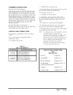
LOW VOLTAGE CONNECTIONS
FOR
DDC CONTROL
Fan Only
Energize G
Cooling Mode
Energize Y, G
Heat Pump Heating
Energize Y, G, B
2nd Stg Heating
Energize G, W2, Y, B
w/Heat Pump (if employed)
Ventilation
Energize G, O1
Emergency Heat
Energize B, W2, E, G
TABLE 3
WALL THERMOSTAT
t
a
t
s
o
m
r
e
h
T
s
e
r
u
t
a
e
F
t
n
a
n
i
m
o
d
e
r
P
9
4
0
-
3
0
4
8
)
0
8
3
-
3
9
F
1
(
t
a
e
h
e
g
a
t
s
3
;
l
o
o
c
e
g
a
t
s
2
c
i
n
o
r
t
c
e
l
E
e
l
b
a
m
m
a
r
g
o
r
P
r
e
v
o
e
g
n
a
h
c
l
a
u
n
a
M
r
o
o
t
u
A
8
5
0
-
3
0
4
8
)
1
5
1
1
D
0
2
2
5
H
T
(
t
a
e
h
e
g
a
t
s
2
;
l
o
o
c
e
g
a
t
s
2
e
l
b
a
m
m
a
r
g
o
r
P
-
n
o
N
c
i
n
o
r
t
c
e
l
E
r
e
v
o
e
g
n
a
h
c
l
a
u
n
a
M
r
o
o
t
u
A
Summary of Contents for SH261
Page 5: ...Manual 2100 409C Page 5 of 25 FIGURE 1 UNIT DIMENSIONS ...
Page 10: ...Manual 2100 409C Page 10 of 25 FIGURE 3 MOUNTING INSTRUCTIONS ...
Page 13: ...Manual 2100 409C Page 13 of 25 FIGURE 7 COMMON WALL MOUNTING INSTALLATIONS ...
Page 20: ...Manual 2100 409C Page 20 of 25 FIGURE 13 DEFROST CONTROL BOARD ...


