


Manual
2100-522B
Page
1 of 38
Bard Manufacturing Company, Inc.
Bryan, Ohio 43506
Since 1914 . . . Moving ahead, just as planned.
Manual:
2100-522B
Supersedes:
2100-522A
File:
Vol II Tab 14
Date:
12-15-11
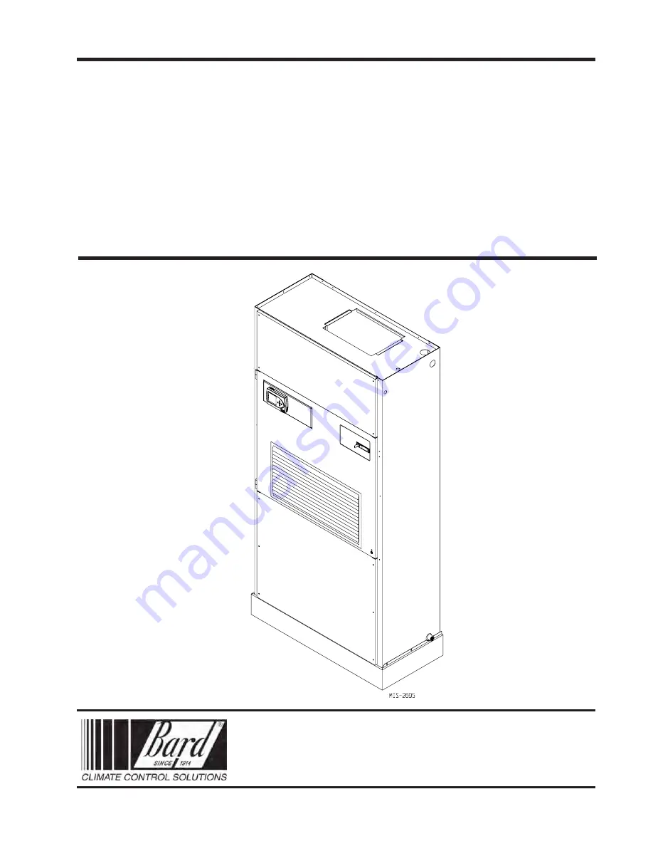
Models:
Q24A1
Q30A1
Q36A1
Q42A1
Q48A1
Q60A1
Q-TEC SERIES
PACKAGED
AIR CONDITIONER
INSTALLATION
INSTRUCTIONS