Bard PH13242-A Installation Instructions Manual Download Page 18

Manual

2100-468E

Page

18 of 27

START UP AND OPERATION

THREE PHASE SCROLL COMPRESSOR
START UP INFORMATION

(Models PH13362-B, PH13422-B, -C; PH13482-B,
-C; PH13602-B, -C)

All units with three phase scroll compressors are equipped
with a three phase line monitor to prevent compressor
damage due to phase reversal.

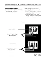
The phase monitor in this unit is equipped with two LED’s.
If the “Y” signal is present at the phase monitor and phases
are correct, the green LED will light.

If phases are reversed, the red fault LED will be lit and
compressor operation is inhibited.

If a fault condition occurs, reverse tow of the supply leads
to the unit.  Do not reverse any of the unit factory wires as
damage may occur.

SEQUENCE OF OPERATION

BLOWER ONLY

  –  When the “Fan” switch on the room

thermostat is placed in the “On” position (circuit R-G
makes), the blower will energize and run until the “Fan”
switch is placed back into the “Auto” position.  This will
allow for constant air circulation at a lower airflow during
times when the unit is not in operation for cooling or
heating.

COOLING

  –  On a call for cooling from the room

thermostat (circuit R-Y makes), the blower will energize
(circuit R-G is automatic when R-Y makes) as well as the
compressor, and outdoor fan motor.  Note that if the “Fan”
switch on the room thermostat is in the “On” position and
the blower is already in operation, then the motor will ramp
up to the required speed for cooling.

HEATING (1st Stage)

  –  On a call for heating from the

room thermostat (circuit R-Y&B makes), the blower will
energize (circuit R-G is automatic when R-Y makes) as
well as the compressor, outdoor fan motor, and reversing
valve solenoid coil.  This will place the system into heat
pump operation to maintain the thermostat set temperature.
Note that if the “Fan” switch on the room thermostat is in
the “On” position and the blower is already in operation,
then the motor will ramp up to the required speed for
heating.

HEATING (1st Stage Defrost)

  –  During the defrost

cycle, the heat pump control will energize electric heaters,
if installed, (circuit R-W2 makes), allowing room
temperature to be maintained during heat pump defrost
operation.

HEATING (2nd Stage)

  –  If the operation of the heat

pump will not maintain the set room temperature, then the
thermostat will call for additional heat from electric heaters
to help maintain the set temperature.  On a call for second
stage heating from the room thermostat (circuit R-W2
makes), backup electric heaters will be energized if
installed.

HEATING (Em Heat)

  –  When the room thermostat is

placed in the “Em Heat” position (circuit R-E makes), the
blower and electric heaters, if installed, will energize on
second stage heat (circuit R-W2&W3 makes), with the
compressor and outdoor fan motor locked out of operation.

Summary of Contents for PH13242-A

Page 1: ...anual 2100 468E Supersedes 2100 468D File Volume II Tab 11 Date 05 28 09 Bard Manufacturing Company Inc Bryan Ohio 43506 Since 1914 Moving ahead just as planned MODELS PH13242 A PH13302 A PH13362 A PH...

Page 2: ...onnections 26 Figure 13 Wiring Connections Voltage 27 Start Up and Operation General 17 Topping Off System Charge 17 Safety Practices 17 Start Up Notes 17 Three Phase Scroll Compressor Start Up Inform...

Page 3: ...ter and Summer Air Conditioning Duct Design for Residential ACCA Manual D Winter and Summer Air Conditioning and Equipment Selection FOR MORE INFORMATION CONTACT THESE PUBLISHERS ACCA Air Conditioning...

Page 4: ...with any separate equipment required to make up the entire heat pump system should be carefully read before beginning the installation Note particularly Starting Procedure and any tags and or labels...

Page 5: ...c S l l o r c S l l o r c S l l o r c S l l o r c S l l o r c S l l o r c S l l o r c S l l o r c S l l o r c S l l o r c S l l o r c S s t l o V 8 0 2 0 3 2 8 0 2 0 3 2 8 0 2 0 3 2 8 0 2 0 3 2 8 0 2...

Page 6: ...0 2 0 4 2 X 1 X 1 9 0 B 3 2 3 P H E 3 8 0 2 0 4 2 X 5 1 B 3 2 3 P H E 3 8 0 2 0 4 2 X 2 5 0 A 3 1 5 P H E 1 8 0 2 0 4 2 X X X 0 1 A 3 1 5 P H E 1 8 0 2 0 4 2 X X X 5 1 A 3 1 5 P H E 1 8 0 2 0 4 2 X 1...

Page 7: ...e v O x a M t n e r r u C n o i t c e t o r P 2 d l e i F r e w o P g n i r i W 3 d n u o r G e z i S e r i W 5 0 A 3 2 3 P H E 0 1 A 3 2 3 P H E 5 1 A 3 2 3 P H E 1 8 0 2 0 4 2 1 8 0 2 0 4 2 1 8 0 2...

Page 8: ...air intake grille intake grille access door Blower motor Condenser fan G 47 11 16 H Unit Dimension Chart MIS 2142 A A C B C H height L length W width D E F G PA PH1324 1330 1336 5 875 32 875 13 875 3...

Page 9: ...while greater elevation may be required for areas of high snow accumulation Poured concrete steel framework brick cement block etc can be utilized to construct a suitable raised mounting platform See...

Page 10: ...e and ressor Blower Motor Heater Package Blower Compressor from top units only Condenser fan and motor access above fan Leave 60 min Side View View Top between duct and any combustible material if dis...

Page 11: ...ORMS Both legs must rest on surface of platform 32 F or lower climate 12 min if in 48 min 48 min 32 F or lower climate 12 min if in on surface of platform Both legs must rest Platform can be as shown...

Page 12: ...pped with a coupling that must be piped through a condensate drain trap to a suitable drain C Always mount the unit is such a position that it may be easily reached for servicing and maintenance D Ins...

Page 13: ...pecified maintain the reversing valve energized when switched into heating mode does not cycle with demand TABLE 7 THERMOSTAT WIRE SIZE t a t s o m r e h T s e r u t a e F t n a n i m o d e r P 8 5 0...

Page 14: ...o Refer to the National Electrical Code for complete current carrying capacity data on the various insulation grades of wiring material The unit rating plate lists a Maximum Time Delay Fuse or HACR ty...

Page 15: ...irable not advantageous in terms of efficiency Since most equipment at time of manufacture is not designated for any specific destination of the country and most of the equipment is installed in areas...

Page 16: ...0 3 2 1 B 2 6 3 3 1 H P 9 0 0 3 2 3 A 2 2 4 3 1 H P 0 1 5 0 0 3 2 1 C B 2 2 4 3 1 H P 9 0 0 6 4 0 3 2 3 A 2 8 4 3 1 H P 0 1 5 0 0 3 2 1 C B 2 8 4 3 1 H P 9 0 0 6 4 0 3 2 3 A 2 0 6 3 1 H P 0 1 5 0 0 3...

Page 17: ...arges R 410A refrigerant is close to being an azeotropic blend it behaves like a pure compound or single component refrigerant The remaining refrigerant charge in the system may be used after leaks ha...

Page 18: ...e room thermostat is in the On position and the blower is already in operation then the motor will ramp up to the required speed for cooling HEATING 1st Stage On a call for heating from the room therm...

Page 19: ...urer s recommendation is for 60 minute defrost cycles There is a cycle speed up jumper on the control This can be used to reduce the time between defrost cycle operation without waiting for time to el...

Page 20: ...o y a l e r n a f s s o r c a k c e h C l o r t n o c p m u p t a e h e c a l p e R e v i t c e f e d r o t o M r o t o m e c a l p e R g n i d n i w r o t o m d e t r o h s r o n e p o r o f k c e h...

Page 21: ...7 4 0 8 4 0 9 4 0 0 5 5 8 9 6 5 4 8 2 5 5 0 4 6 3 5 1 5 0 2 5 4 1 5 0 5 8 2 0 9 4 0 9 5 7 4 0 0 2 6 4 5 5 8 4 4 4 5 5 3 4 5 9 2 2 4 7 7 0 1 4 8 9 8 9 3 7 5 7 8 3 2 5 6 7 3 3 8 5 6 3 8 4 5 5 3 5 4 5 4...

Page 22: ...power fuses or circuit breakers to be sure that they are the correct rating 5 Periodic cleaning of the outdoor coil to permit full and unrestricted airflow circulation is essential PRESSURE SERVICE PO...

Page 23: ...g i H 7 3 1 2 5 2 8 3 1 6 7 2 0 4 1 9 9 2 1 4 1 3 2 3 2 4 1 7 4 3 4 4 1 0 7 3 5 4 1 4 9 3 6 4 1 0 2 4 8 4 1 6 4 4 9 4 1 2 7 4 1 5 1 8 9 4 2 5 1 4 2 5 3 5 1 0 5 5 5 8 B D 2 7 B W e d i S w o L e d i S...

Page 24: ...w o L e d i S h g i H 6 3 1 1 5 2 7 3 1 4 7 2 9 3 1 8 9 2 0 4 1 1 2 3 1 4 1 4 4 3 3 4 1 8 6 3 4 4 1 1 9 3 5 4 1 2 2 4 5 4 1 2 5 4 6 4 1 3 8 4 6 4 1 3 1 5 7 4 1 4 4 5 8 4 1 5 7 5 5 8 B D 2 7 B W e d i...

Page 25: ...y around the circumference to flow braze material completely around the joint Slowly move torch into Area 3 to draw braze material into joint See Figure 11 Do not overheat joint FIGURE 11 BRAZING DIAG...

Page 26: ...within the ranges as listed on the unit serial plate If higher than allowed additional duct work is needed e If the motor does not shut off at the end of the cycle wait for any programmed delays to t...

Page 27: ...nd the appropriate motor terminal 1 5 G input is typically on terminal 1 but refer to wiring diagram a If the low voltage communication is not present check the demand from the thermostat Also check t...

Reviews: