Page
1 of 68
Bard Manufacturing Company, Inc.
Bryan, Ohio 43506
www.bardhvac.com
Manual: 2100-749Supersedes:
NEW
Date: 2-3-21
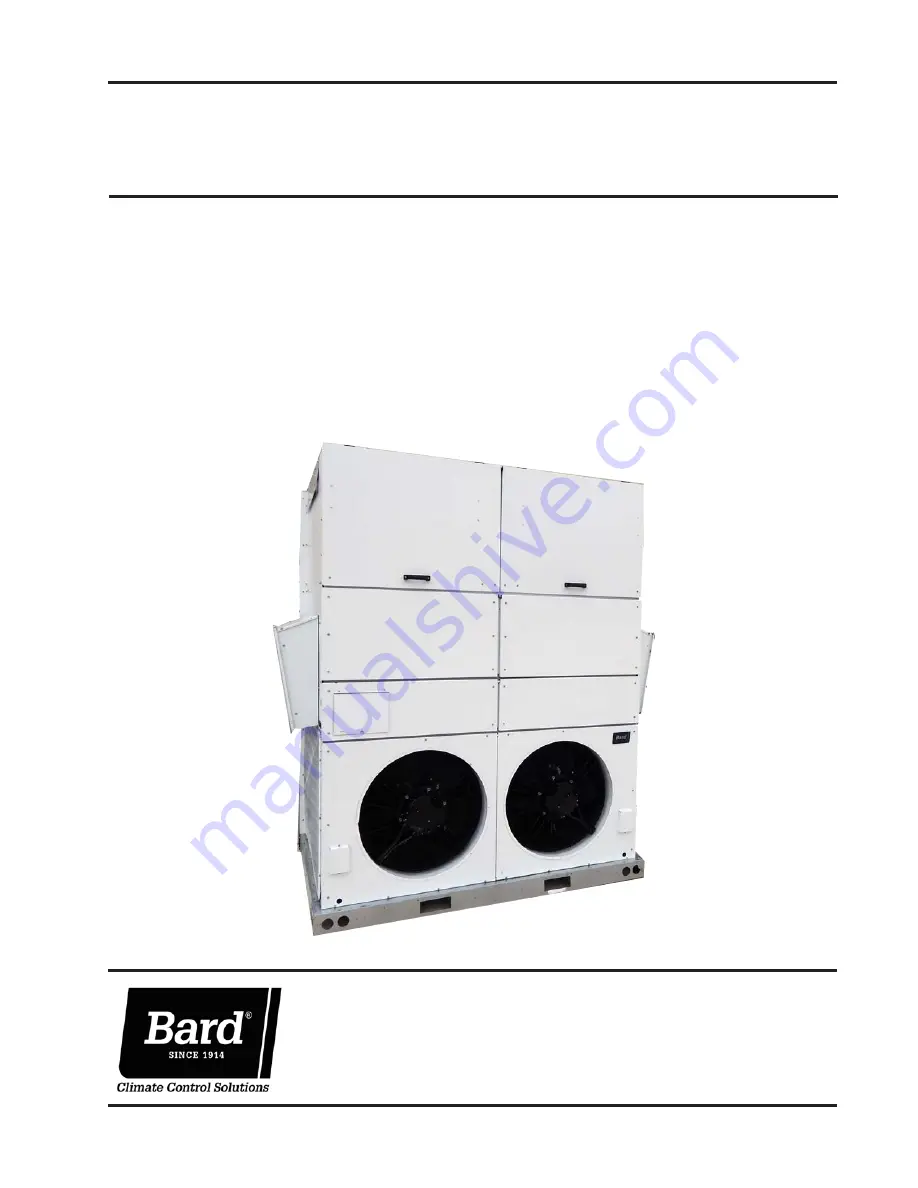
SERVICE INSTRUCTIONS
MEGA-TEC
®
Wall-Mount Air Conditioner
Models: W180B
Page 1: ...Page 1 of 68 Bard Manufacturing Company Inc Bryan Ohio 43506 www bardhvac com Manual 2100 749 Supersedes NEW Date 2 3 21 SERVICE INSTRUCTIONS MEGA TEC Wall Mount Air Conditioner Models W180B ...
Page 2: ... Air Temperature Sensor Alarm 23 Condenser Fan 23 Condenser Fan Components 23 Condenser Fan 23 Liquid Pressure Sensor 24 Troubleshooting the Discharge Liquid Pressure Transducer 24 Discharge Liquid Pressure Transducer Alarm 24 Liquid Temperature Sensor 24 Outdoor Temperature Sensor 25 Condenser Fan Operation 25 Condenser Fan Speed Control 25 Compressor 25 Compressor Components 25 Compressor 25 Com...
Page 3: ...us 28 Figure 42 Overriding Compressor Outputs 29 Figure 43 Damper Override 29 Figure 44 Dust Sensor 30 Figure 45 Verifying Dust Sample Output Status 30 Figure 46 Overriding Dust Sample Output 30 Figure 47 Adjusting Dust Sensor Alarm Setpoint 31 Figure 48 W180 Damper Blades 31 Figure 49 Damper Blade Position 32 Figure 50 Damper Switch 32 Figure 51 Outdoor Temperature Sensor 33 Figure 52 Outdoor Hum...
Page 4: ...ioning system should be carefully read before beginning the installation Note particularly any tags and or labels attached to the equipment While these instructions are intended as a general recommended guide they do not supersede any national and or local codes in any way Authorities having jurisdiction should be consulted before the installation is made See Additional Publications for informatio...
Page 5: ...DANGER is to be limited to the most extreme situations DANGER signs should not be used for property damage hazards unless personal injury risk appropriate to these levels is also involved WARNING Indicate s a hazardous situation which if not avoided could result in death or serious injury WARNING signs should not be used for property damage hazards unless personal injury risk appropriate to this l...
Page 6: ...lt setpoints and their ranges are easily viewed and adjusted from the TEC EYE display The program and operating parameters are permanently stored on FLASH MEMORY in case of power failure The TEC EYE connects to the wall mount unit control board via an RJ11 modular phone connector as shown in Figure 2 ALARM KEY Allows viewing of active alarms Silences audible alarms Resets active alarms MENU KEY Al...
Page 7: ...formation and Alarm Log are available through the Quick Menu Pressing the UP or DOWN keys while on the main Status screen will change the Quick Menu icon displayed see Figure 3 Press the ENTER key when the desired icon is displayed User 2000 Technician 1313 Engineer 9254 Use UP or DOWN keys and ENTER key to enter password The passwords listed above are the default passwords End users can change th...
Page 8: ...nit is operating the electric heaters to warm the space Optimized This message will be shown when the unit is operating both the economizer and the air conditioning simultaneously to cool the space Active Dehum This message will be shown when the unit is connected to the LC6000 or stand alone display no heating or cooling calls are required and the air conditioner and electric heat are being used ...
Page 9: ...are a single return air temperature sensor located in the return duct opening but each air path has its own mixed air temperature sensor and supply air temperature sensor Unit air path and outdoor conditions can be found on three screens within the information menu see Figure 6 The information and measurements provided are return air temperature air path specific mixed air temperature economizer e...
Page 10: ...e found in four screens within the information menu see Figure 8 The information and measurements provided are liquid line temperature liquid line pressure condensing saturated temperature suction line temperature suction line pressures suction saturated temperature super heat subcooling and electronic expansion valve position 24 Hour Run Time The Last 24 Hour Tracking screens display unit run tim...
Page 11: ...of step times self test parameters are not adjustable The self test will automatically skip sections of the test based on the model number entered into the controller If position 10 of the model number is B to indicate no vent option the economizer open and close steps will be skipped If positions 8 and 9 of the model number indicate a 0Z 0 kW option steps G H and I will be skipped If position 8 a...
Page 12: ...ER key to scroll to Reset to Factory Defaults see Figure 11 7 Press UP or DOWN key to change value to YES press ENTER key 8 System will restart with default values The controller can only be factory reset when the USB port is not in use When the USB port is in use a message will appear and the option to reset factory defaults will not be available see Figure 12 Configuration File The controller wi...
Page 13: ...hat backlights the ALARM function key An alarm is acknowledged by pressing the ALARM key This calls up alarm display screen s that provide a text message detailing the alarm condition s Clearing Alarms Alarms can only be cleared after the alarm condition has been corrected To clear a single alarm press and hold the ALARM key for 3 seconds while viewing a specific alarm screen To clear all alarms n...
Page 14: ...r the space temperature when the unit is in orphan mode The return air sensor is located in the return opening for air path circuit 1 in such a way that it is exposed to the entering airstream An alarm signal will be sent to the LC controller if the return air temperature sensor is disconnected The temperature is measured with a 10k ohm NTC thermistor This sensor can be verified and adjusted by 1 ...
Page 15: ...ount unit s will go into orphan mode and operate using the last communicated setpoints To change default setpoints refer to Setpoints on page 7 During installation the ability to run in orphan mode allows deactivation of one of the existing older wall mount units while keeping the shelter cool with the other unit still operating Once the first of the Bard wall mount units is installed and powered ...
Page 16: ...Full Capacity FIGURE 20 Adjusting Cooling Differentials Heating The unit will use up to 2 stages of electric heat to heat the space see Figure 19 Electric heat is available as an option and the heating capacity will determine the number of stages see Electric Heat Option on page 37 To view or adjust the heating differentials 1 Press MENU key to go to the Main Menu screen 2 Press UP or DOWN keys an...
Page 17: ...ey to scroll to Enable 10 Press UP or DOWN key to change Off to On 11 Press ENTER key to save After the service or troubleshooting is completed use TEC EYE to disable the EEV manual positioning override and turn unit back on The valve can also be opened or closed using the EEV service tool Bard Part 2151 021 This magnetic EEV service tool shown in Figure 23 is used to manually open the EEV To do t...
Page 18: ...d out of the Offset parameter 10 Once adjusted press the ESCAPE key several times to return to Main Menu screen Troubleshooting the Suction Pressure Transducer 0 250 psig 5v Nominal 5 4 5v Actual 4v 250 psig 016 volts per 1 psig Example 125 psig x 016 5 volts 2 5 volts Formula for Tech Measured Pressure x 016 Voltage Offset Expected Transducer Signal Voltage see Figure 25 FIGURE 24 Adjusting Sucti...
Page 19: ...ndition is no longer present This alarm cannot be adjusted TABLE 5 Unit Specific Superheat Setpoints Unit Superheat W180B 12 F Indoor Airflow Indoor Airflow Components Blower The unit is equipped with a blower that is driven by an electronically commutated motor ECM The blower is controlled by a 0 100 signal through Modbus communication The motor controller converts this signal to a PWM signal The...
Page 20: ...tic Pressure WC N0Z N09 N18 N36 1 00 1 00 1 00 1 00 Q0Z Q09 Q18 Q36 1 00 1 00 1 00 1 00 S0Z S09 S18 S36 1 00 1 00 1 00 1 00 T0Z T09 T18 T36 1 00 1 00 1 00 1 00 TABLE 7 Indoor Blower Performance ESP Inch H20 Dry Coil Wet Coil W180B 0 35 8190 N A FIGURE 29 Verifying Differential Airflow Status FIGURE 28 Dirty Filter Switch and Blower Status Switch Left and Right Dirty Filter Switches W180 Set 1 40 L...
Page 21: ...e filter through silicone tubing routed to the blower and evaporator areas of the unit The switch circuit consists of a normally closed filter pressure switch The switch will open when the pressure differential goes above the setting indicated on the dial When the pressure difference returns below the setting on the dial the switch will close Adjustment of dirty filter switch may be necessary to e...
Page 22: ...press ENTER key 4 Press UP or DOWN keys to scroll to Digital Outputs press ENTER key 5 Press UP or DOWN keys to scroll to Digital Outputs C2 5 6 Press ENTER key to scroll to Enable Override see Figure 32 7 Press UP or DOWN key to change value to Yes FIGURE 32 Overriding Filter Light Output 8 Press ENTER key to scroll to Filter Light 9 Press UP or DOWN key to change value to On or Off Indoor Airflo...
Page 23: ... Balanced Climate or High Sensible parameter see Figure 33 6 Press UP or DOWN key to change value from Off to On or On to Off FIGURE 33 Enabling Disabling High Sensible Operation or Balanced Climate Operation The unit will automatically switch to the required speed for each mode For more information on the high sensible command from LC please see LC6000 Service Instructions 2100 669 Additional Ind...
Page 24: ...effect until the cursor is moved out of the offset parameter 9 Once adjusted the ESCAPE key several times to return to Main Menu screen Troubleshooting the Discharge Liquid Pressure Transducer 0 650 psig 5 to 4 5v 4 5 5 4 volt range 650 psig 00615 volts per 1 psig Example 325 psig x 00615 5 v 2 5 volts Formula for Tech Measured Pressure x 00615 Voltage Offset Expected Transducer Signal Voltage see...
Page 25: ...However three phase compressors will rotate in either direction depending upon phasing of the power Since there is a 50 50 chance of connecting power in such a way as to cause rotation in the reverse direction verification of proper rotation must be made Verification of proper rotation direction is made by observing that suction pressure drops and discharge pressure rises when the compressor is en...
Page 26: ... be removed for testing The conditions needed for the unit to enter test mode are as follows POT must start at a time less than or equal to the 40 second mark The POT must then be rapidly rotated to a position greater than or equal to the 280 second mark in less than second Normal operation will resume after power is reset or after the unit has been in test mode for at least 5 minutes Brownout Pro...
Page 27: ... set 30 pounds below high pressure switch which is 650 the system will disable stage 2 of mechanical cooling Phase Monitor Used only on three phase equipment the phase monitor is a compressor protection device that will prohibit operation of the compressor if the device senses a possible reverse rotation situation due to incorrect phasing On a call for compressor and only compressor the device wil...
Page 28: ...f the compressor in regards to the cooling demand The compressor has a minimum on time of 180 seconds to prevent short cycling the compressor The compressor also has a minimum off time of 120 seconds to prevent start ups before the pressure in the refrigeration system equalizes When the second stage is engaged it also has a minimum run time of 120 seconds to allow the system to stabilize before re...
Page 29: ...uators The left intake damper damper 1 and the right intake damper damper 3 are each powered by a 44 in lb actuator The left exhaust damper damper 2 and right exhaust damper damper 4 are powered by a 90 in lb actuator All dampers are spring return and will close the damper if power is lost To verify the output from the controller to the actuator 1 Press MENU key to go to the Main Menu screen 2 Pre...
Page 30: ... override will only stay active for 5 minutes To override the dust sample output 1 Press MENU key to go to the Main Menu screen 2 Press UP or DOWN keys and ENTER key to enter TECHNICIAN password 1313 3 Press UP or DOWN keys to scroll to I O Config press ENTER key 4 Press UP or DOWN keys to scroll to Digital Outputs press ENTER key 5 Press UP or DOWN keys to scroll to Digital Outputs C2 7 6 Press E...
Page 31: ... dust sensor alarm setpoint 1 Press MENU key to go to the Main Menu screen 2 Press UP or DOWN keys and ENTER key to enter USER password 2000 3 Press UP or DOWN keys to scroll to System Config press ENTER key 4 Press UP or DOWN keys to scroll to Dust Configuration A4 5 Press ENTER key to scroll to Alarm Set see Figure 47 6 Press UP or DOWN keys to change to the desired value 7 Press ENTER key to sa...
Page 32: ...TER key to enter TECHNICIAN password 1313 3 Press UP or DOWN keys to scroll to I O Config press ENTER key 4 Press UP or DOWN keys to scroll to Analog Outputs press ENTER key 5 Press UP or DOWN keys to scroll to Analog Outputs C4 1 damper 1 Analog Outputs C4 2 damper 2 Analog Outputs C4 3 damper 3 or Analog Outputs C4 4 damper 4 See Figure 49 Damper Failed to Open Alarm When the controller commands...
Page 33: ... scroll to Analog Ins C3 5 6 Reference the Value to see the input of the sensor see Figure 52 7 To apply an offset press ENTER key to scroll to Offset Outdoor Temperature Sensor Failure Alarm When the sensor reads a value that is outside of the acceptable 41 to 303 0 range an alarm will be generated indicating the sensor has failed This alarm condition will disable the economizer This alarm is fix...
Page 34: ...tup type on Economizer Setup A2 will automatically change to None The only exception to this is emergency ventilation will always attempt to open the dampers This would only apply if a unit has an economizer but the controller is configured for no vent B The economizer has four types of operation The first mode is None where the economizer is never utilized except for emergency purposes The second...
Page 35: ...d 22 Press ENTER key to save the value and scroll to OA Hum Set 23 Press UP or DOWN keys to adjust the humidity setpoint to desired value 24 Press ENTER key to save the value and scroll to On Diff 25 Press UP or DOWN keys to adjust the outdoor humidity differential for which the economizer is re enabled 26 Press ENTER key to save the value and scroll to Dew Pt Set 27 Press UP or DOWN keys to adjus...
Page 36: ...e Miscellaneous Components Supply Temperature Sensor The unit is equipped with two supply air temperature sensors located in the supply opening of each air path to monitor the leaving air temperature of the unit The temperature is measured with a 10k ohm NTC thermistor The supply air temperature can be verified by 1 Press MENU key to go to the Main Menu screen 2 Press UP or DOWN keys and ENTER key...
Page 37: ...mergency Cool Orphan Mode FIGURE 60 Adjusting Return Air Alarm Settings Emergency Ventilation Mode If the emergency ventilation input at the LC is active the system will go into emergency ventilation mode In emergency ventilation mode the economizers on the wall units will be commanded to 100 This mode is only available when connected to the LC NOTE All units will receive the emergency ventilation...
Page 38: ...model number entered into the wall mount unit s controller This parameter will show either Not Available or Electric Reheat 5 Press ENTER key to scroll to Enable 6 Press UP or DOWN keys to change the value from Yes to No An electric reheat capable unit will allow for concurrent operation of compressor and electric heat This allows the compressor to operate which will remove moisture from the indoo...
Page 39: ...information on dehumidification staging see latest version of LC6000 Service Instructions manual 2100 669 FIGURE 64 Dehumidification Control F 58 Reheat Cool 59 60 61 62 63 64 65 66 67 68 69 70 71 72 73 74 75 76 77 78 79 Unit Disable Option The wall mount unit can be disabled by opening a dry set of contacts connected to Input DI1 on the PLC board This feature can be used in addition to the emerge...
Page 40: ...on MEGA TEC wall mount units configure some settings based on the model number that is input into the unit The model and serial number are entered at the factory and should be retained during a software update However after a software update it is best practice to verify that the model number and serial number are still present and accurate If the model number and or serial number is missing or in...
Page 41: ...odel number 6 Press UP or DOWN keys to change value of the digit 7 Continue Steps 5 and 6 until the serial model number s are correct and reflect the number on the product label For more information on the options and settings available for specific model numbers see the model number breakdown in Figure 69 on page 42 ...
Page 42: ... 230 208 60 3 220 200 50 3 T 460 60 3 415 380 50 3 kW 0Z O kW with Circuit Breaker 09 9 kW with Circuit Breaker 18 18 kW with Circuit Breaker 36 36 kW with Circuit Breaker VENT B No Vent E Economizer DB and WB FILTER M MERV11 Disposable P MERV8 2 Pleated N MERV13 2 Pleated COLOR X Beige Baked Enamel Finish 1 White Baked Enamel Finish 4 Gray Baked Enamel Finish COIL AND UNIT COATING OPTIONS X Stand...
Page 43: ...nk as a liquid to avoid any fractionation and to insure optimal system performance Refer to instructions for the cylinder that is being utilized for proper method of liquid extraction Safety Practices 1 Never mix R 410A with other refrigerants 2 Use gloves and safety glasses Polyol ester oils can be irritating to the skin and liquid refrigerant will freeze the skin 3 Never use air and R 410A to le...
Page 44: ...ed condenser fan operation If condensing pressures appear elevated check condenser fan wiring See Condenser Fan Operation on page 25 Cooling Air Temperature Entering Outdoor Coil F Model Return Air Temp DB WB Pressure 75 80 85 90 95 100 105 110 115 120 125 131 W180 Stage 31 75 62 Low Side 126 127 128 129 130 131 132 133 134 135 136 138 High Side 315 340 364 388 412 435 459 481 504 526 548 573 80 6...
Page 45: ...upply louvers if necessary to direct discharge air away from any direct route to the return grille 9 Re assemble wall mount unit remembering to fasten fan to mounting brackets Turn breakers back on 10 Enable system to LC6000 controller see latest revision of LC6000 Service Instructions 2100 669 11 Repeat steps for additional wall mount units 1 Disable system from LC6000 controller see latest revis...
Page 46: ... SENSOR 5030 008 0300 7950 021 8406 158 PART THEN WRAP WITH 6 PRESSTITE TAPE PART 5030 008 0600 TRANSDUCER 910 2084 LLT1 LIQUID TEMP SENSOR SECURE ST1 SENSOR TO LINE WITH HOSE CLAMP PART HIGH PRESSURE TRANSDUCER PART 8406 157 DUST SENSOR CONTROL BOARD ECONOMIZER ONLY MAT MIXED AIR SENSOR PART 910 2156 ECONOMIZER ONLY 8406 158 HIGH PRESSURE PART TRANSDUCER 8406 157 LOW PRESSURE TRANSDUCER PART PANE...
Page 47: ...Manual 2100 749 Page 47 of 68 FIGURE 71 Supply and Return Air Sensors Supply Air Sensors Return Air Sensor ...
Page 48: ...3 connector The thermocouple wires are loose in the sensor housing and require a butt splice connector or wire nut to connect to the main unit wiring harness See Figures 72 and 73 for sensor wiring and terminal location Tables 13 and 14 on pages 50 and 52 are correlation charts for troubleshooting the sensor with a test meter Table 13 Temperature to Thermocouple Resistance Table 14 Relative Humidi...
Page 49: ...weather data to find ambient temperature conditions FIGURE 74 8301 089 Sensor Temperature Probe Troubleshooting 4 Using an ohmmeter or resistance mode on a multimeter measure resistance across white leads leading to the temperature sensor see Figure 74 5 Cross reference readings with Table 13 on page 50 A If readings are consistent with reference temperature check wiring or offset in PLC if outdoo...
Page 50: ...23 466 62 42 5 6 22 886 87 43 6 1 22 323 22 44 6 7 21 775 16 45 7 2 21 242 23 46 7 8 20 723 96 47 8 3 20 219 91 48 8 9 19 729 65 49 9 4 19 252 76 50 10 0 18 788 84 Temperature Resistance F C Ω 51 10 6 18 337 51 52 11 1 17 898 38 53 11 7 17 471 09 54 12 2 17 055 30 55 12 8 16 650 65 56 13 3 16 256 82 57 13 9 15 873 48 58 14 4 15 500 34 59 15 0 15 137 09 60 15 6 14 783 44 61 16 1 14 439 11 62 16 7 1...
Page 51: ...he humidity sensor to return to normal operation FIGURE 75 8301 089 DIP Switch Output Configuration FIGURE 76 8301 089 Sensor Humidity Probe Troubleshooting 8301 089 Outdoor Humidity Sensor Troubleshooting To verify sensor operation 1 Remove lid from outdoor temperature humidity sensor 2 Loosen and remove black wire from the 4 20 mA input of TB1 see Figure 73 on page 48 3 Use an RH meter preferred...
Page 52: ...8 16 480 mA 79 16 640 mA 80 16 800 mA 81 16 960 mA 82 17 120 mA 83 17 280 mA 84 17 440 mA 85 17 600 mA 86 17 760 mA 87 17 920 mA 88 18 080 mA 89 18 240 mA 90 18 400 mA 91 18 560 mA 92 18 720 mA 93 18 880 mA 94 19 040 mA 95 19 200 mA 96 19 360 mA 97 19 520 mA 98 19 680 mA 99 19 840 mA 100 20 000 mA TABLE 14 8301 089 Sensor Humidity mA RH mA Output 34 9 440 mA 35 9 600 mA 36 9 760 mA 37 9 920 mA 38 ...
Page 53: ... 101 0 5697 12 0 126219 26 0 38757 64 0 13820 102 0 5570 11 0 122089 27 0 37652 65 0 13474 103 0 5446 10 0 118108 28 0 36583 66 0 13137 104 0 5326 9 0 114272 29 0 35548 67 0 12810 105 0 5208 8 0 110575 30 0 34545 68 0 12492 106 0 5094 7 0 107010 31 0 33574 69 0 12183 107 0 4982 6 0 103574 32 0 32634 70 0 11883 108 0 4873 5 0 100260 33 0 31723 71 0 11591 109 0 4767 4 0 97064 34 0 30840 72 0 11307 1...
Page 54: ...fferential Switch Terminals 1 Normally Closed 2 Normally Open 3 Common NOTE Contact position is in resting state P2 P1 Connect hose to P2 Hoses need to be connected to the P2 port port closest to front W180 Switch Settings Left and Right Blower Status Switches 0 40 Left and Right Dirty Filter Switches 1 40 ...
Page 55: ...olenoid pulls in Remove power and listen for another click as the solenoid returns to its original position 3 If clicks can t be heard shut off power remove the control circuit molded plug from the compressor and measure the solenoid coil resistance 1640 ohms 4 Next check the molded plug Voltage Check Apply control voltage to the plug wires 18 to 28 VAC The measured DC voltage at the female connec...
Page 56: ...sensor communication cable from the dust sensor connector on the dust sensor alarm board and the dust sensor see Figure 79 B Inspect communication cable for the following i Wires pulled out of the connectors ii Scars in insulation exposing bare wire C If communication cable is damaged i Replace communication cable D If communication cable is not damaged i Carefully reconnect the dust sensor commun...
Page 57: ...82 36 1 86 37 1 91 38 1 96 39 2 01 40 2 06 41 2 11 42 2 16 43 2 21 44 2 26 45 2 31 46 2 35 47 2 40 48 2 45 49 2 50 50 2 55 51 2 60 52 2 65 53 2 70 54 2 75 55 2 80 56 2 84 57 2 89 58 2 94 59 2 99 60 3 04 61 3 09 62 3 14 63 3 19 64 3 24 65 3 29 66 3 33 67 3 38 Dust Signal µg m3 Vdc 68 3 43 69 3 48 70 3 53 71 3 58 72 3 63 73 3 68 74 3 73 75 3 78 76 3 82 77 3 87 78 3 92 79 3 97 80 4 02 81 4 07 82 4 12...
Page 58: ...oltage to the unit ensuring that it cannot be switched back on inadvertently and wait 5 minutes before removing terminal covers Wait until fan blower comes to a complete stop before entering areas After work is performed verify all tools have been removed from unit and specifically the rotational area of the fan blower FIGURE 80 Fan Terminals Connector Terminal Description CON1 L1 Line Power Phase...
Page 59: ...terminal cover of the blower fan assembly Green No warning of fault of Pulses Motor Status Manual Reset Required Possible Cause Possible Remedy 1 Phase Failure Line Under Voltage No Missing phase poor line voltage quality Check line voltage 3 Inverter Output Overheating Yes Dirty electronics housing Clean inverter housing improve cooling 4 Communication Error No External power supplied to V out fo...
Page 60: ...wires landed on them and terminals 27 32 should only have black wires landed on them see Figure 84 FIGURE 83 Blower Condenser Fan Communication Wires For the blower s and condenser fan s The clear white wire should land on the RSA terminal and the black wire should land on the RSB terminal See Figure 83 Control Panel Terminal Modbus Device Terminal Modbus Device 21 FB Main Controller PLC 27 FB 22 ...
Page 61: ... correct DIP switch settings on the c pCOe see Figure 86 3 If problem persists verify 24VAC power to c pCOe disconnect communication plug from c pCOe and disconnect wires from terminal block Verify continuity from end to end and then verify there are no shorts to ground 4 To verify the expansion module C PCOe is faulty the communication wires should be isolated from the blower and condenser fan an...
Page 62: ...found replace blower motor Condenser Fan Communication Failure For the following steps use the TEC EYE to view the Modbus status of the condenser fan This screen is accessible in the I O Menu under Fans Blowers see Figure 88 1 Remove condenser fan terminal access cover if not already done 2 Verify high voltage to condenser fan on terminals L1 L2 and L3 with a volt meter A If incorrect or no voltag...
Page 63: ...cuit 2 Supply Air Temperature Sensor Alarm See Indoor Airflow section 16 Circuit 2 High Supply Air Temperature Alarm See Indoor Airflow section 17 Circuit 2 Low Supply Air Temperature Alarm See Indoor Airflow section 18 Outdoor Air Temperature Sensor Alarm See Economizer section 19 Outdoor Air Humidity Sensor Alarm See Economizer section 20 Circuit 1 Dust Sensor Alarm See Economizer section 21 Cir...
Page 64: ... 1 Freeze Condition See Electronic Expansion Valve EEV section 51 Circuit 2 Freeze Condition See Electronic Expansion Valve EEV section 52 Circuit 1 Blower Fail Alarm See Indoor Airflow section 53 Circuit 2 Blower Fail Alarm See Indoor Airflow section 54 Dirty Filter 1 Alarm See Indoor Airflow section 55 Dirty Filter 2 Alarm See Indoor Airflow section 60 Emergency Ventilation Mode Active See Econo...
Page 65: ...ing Error See Electronic Expansion Valve EEV section 86 Circuit 2 Emergency Close See Electronic Expansion Valve EEV section 87 Circuit 2 High Delta Temperature See Electronic Expansion Valve EEV section 88 Circuit 2 High Delta Pressure See Electronic Expansion Valve EEV section 89 Circuit 2 Range Error See Electronic Expansion Valve EEV section 90 Circuit 2 Service Position Percent See Electronic...
Page 66: ...SUPPLY AIR EXHAUST AIR CONDENSER EXHAUST FRESH AIR AIR CONDENSER AIR CONDENSER FRESH AIR SUPPLY AIR RETURN AIR CONDENSER EXHAUST RETURN AIR SUPPLY AIR EXHAUST CONDENSER EXHAUST AIR FRESH AIR AIR CONDENSER AIR CONDENSER FRESH AIR CONDENSER AIR CONDENSER AIR SIDE VIEW FRONT VIEW SIDE VIEW FRONT VIEW SIDE VIEW FRONT VIEW ...
Page 67: ...Manual 2100 749 Page 67 of 68 FIGURE 90 I O Layout I O Layout ...
Page 68: ...Manual 2100 749 Page 68 of 68 FIGURE 91 I O Layout ...