Page
1 of 26
MIS-2498
INSTALLATION INSTRUCTIONS
Bard Manufacturing Company, Inc. Bryan, Ohio 43506www.bardhvac.com
Manual: 2100-646Supersedes:
NEW
Date: 9-3-15
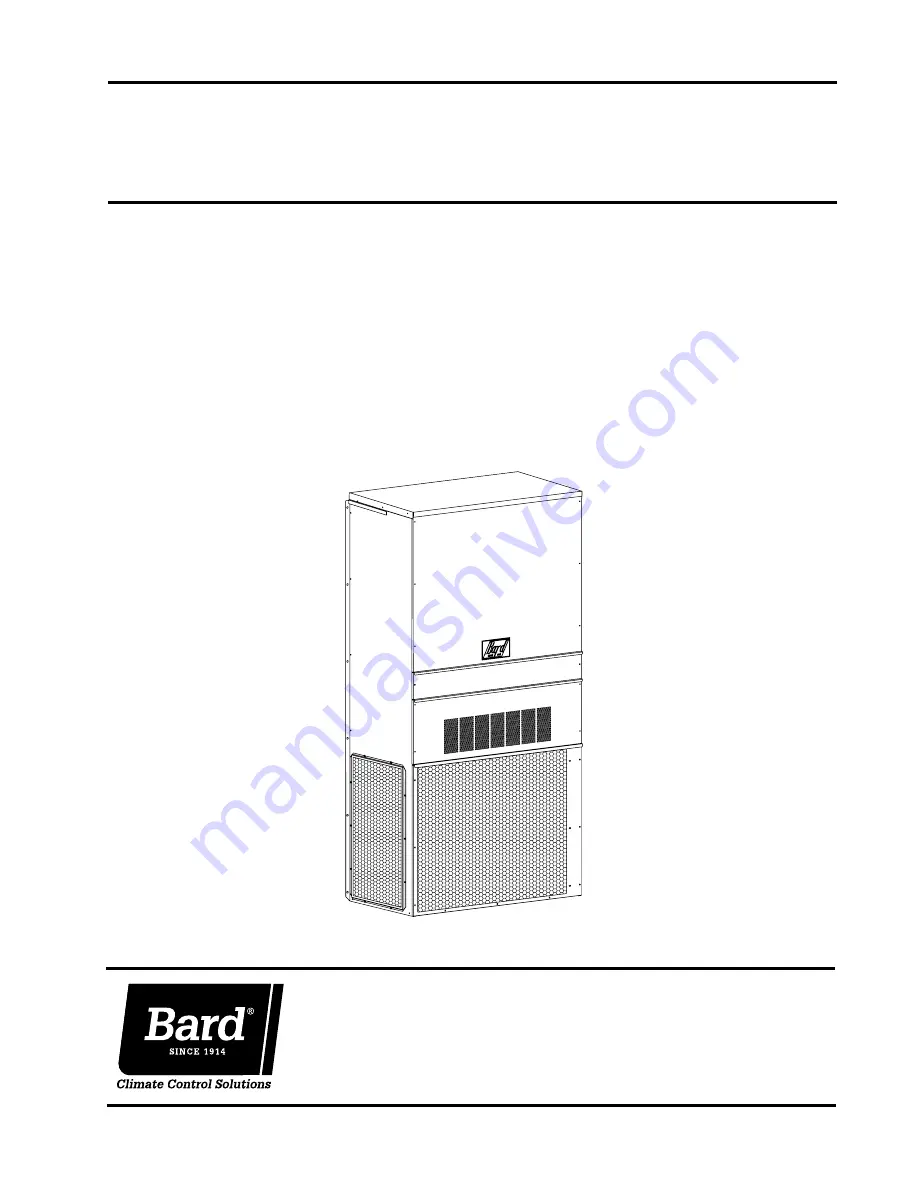
WALL-MOUNTED
PACKAGED AIR CONDITIONER
Models:
HA4S4KAHA5S4KA
HL4S4KAHL5S4KA
Page 1: ...8 INSTALLATION INSTRUCTIONS Bard Manufacturing Company Inc Bryan Ohio 43506 www bardhvac com Manual 2100 646 Supersedes NEW Date 9 3 15 WALL MOUNTED PACKAGED AIR CONDITIONER Models HA4S4KA HA5S4KA HL4S4KA HL5S4KA MIS 2498 ...
Page 2: ...ndoor Blower Performance 22 Table 8 Optional Accessories RH Units 22 Table 9 Optional Accessories LH Units 22 Getting Other Information and Publications 3 Wall Mount General Information 4 Air Conditioner Wall Mount Model Nomenclature 4 Shipping Damage 7 General 7 Duct Work 7 Filters 7 Condensate Drain 7 Installation 8 Wall Mounting Information 8 Mounting the Unit 8 Typical Installations 8 Wiring M...
Page 3: ... 5478 NFPA National Fire Protection Association Batterymarch Park P O Box 9101 Quincy MA 02269 9901 Telephone 800 344 3555 Fax 617 984 7057 These publications can help when installing the furnace They can usually be found at the local library or purchased directly from the publisher Be sure to consult the current edition of each standard National Electrical Code ANSI NFPA 70 Standard for the Insta...
Page 4: ...ailable in 230 208V units only VOLTS PHASE A 230 208 1 KW 0Z No KW w Circuit Breaker or Pull Disconnect 05 5 KW 08 8 KW 10 10 KW 15 15 KW VENTILATION OPTIONS B Blank Off Plate No Ventilation Y 100 Economizer Temperature Z 100 Economizer Enthalpy COLOR OPTIONS X Beige Standard 4 Buckeye Gray 5 Desert Brown 8 Dark Bronze A Aluminum S Stainless Steel OUTLET OPTIONS X Front Standard COIL OPTIONS X Sta...
Page 5: ...ectrical Entrance High Voltage Electrical Entrance Economizer Intake Hood 4 Pitch Lockable Rain Hood Built In Air Inlet Access Panel Cond Heater Electric Heat C Breaker Disconnect Access Panel Drain Side View C H K J I D 2 13 A Vent Option Door 1 1 Condenser Filter Access Panel Air Outlet Ventilation Air Front View F G W 5 75 Condenser Air Outlet I A C K 2 13 H J N Q P M L O E 44 W 5 88 F G R S S ...
Page 6: ...re All wiring must conform to the National Electric Code NEC and all local codes TABLE 3 Electrical Specifications Model Rated Volts and Phase No Field Power Circuits Single Circuit Multiple Circuit Minimum Circuit Ampacity j Maximum External Fuse or Ckt Brkr k Field Power Wire Size Ground Wire Minimum Circuit Ampacity j Maximum External Fuse or Ckt Brkr k Field Power Wire Size Ground Wire Ckt A C...
Page 7: ...ons are at a variance with instructions installer should adhere to local codes DUCT WORK All duct work supply and return must be properly sized for the design airflow requirement of the equipment Air Conditioning Contractors of America ACCA is an excellent guide to proper sizing All duct work or portions thereof not in the conditioned space should be properly insulated in order to both conserve en...
Page 8: ...olt locations and bottom mounting bracket location see Figure 4 4 Mount bottom mounting bracket 5 Hook top rain flashing under back bend of top Top rain flashing is shipped secured to the right side of the back 6 Position unit in opening and secure with 5 16 lag bolts use 7 8 diameter flat washers on the lag bolts 7 Secure rain flashing to wall and caulk across entire length of top see Figure 2 8 ...
Page 9: ...16 1 7 8 6 1 2 6 1 2 2 1 8 7 8 1 3 4 Typ 4 Typ 6 1 2 30 E 16 A C C 3 1 8 B Wall Opening and Hole Location View RETURN AIR 1 REQUIRED DIMENSIONS TO MAINTAIN 1 4 MIN CLEARANCE FROM COMBUSTIBLE MATERIALS REQUIRED DIMENSIONS TO MAINTAIN 29 DUCT COMBUSTIBLE MATERIALS A B C D E 30 1 2 10 1 2 6 1 4 1 1 4 29 3 4 32 12 5 1 2 2 NOTES WALL STRUCTURE 1 SUPPLY AIR IT IS RECOMMENDED THAT A BEAD OF OPENING Right...
Page 10: ... FLASHING SUPPLY AIR MIS 548 A SIDE VIEW I A C K E 1 000 B 1 000 SUPPLY DUCT OVER FRAME INTERIOR FINISHED WALL ALL AROUND DUCT FRAMING MATERIAL EXTERIOR FINISH WALL OPENING FOR ACTUAL DIMENSIONS 2 x 4 S 2 x 6 S OR STRUCTURAL STEEL ATTACH TO TOP 1 000 CLEARANCE 1 000 CLEARANCE PLATE OF WALL C SEE UNIT DIMENSIONS FIGURE 2 OPENING RETURN DUCT 2 x 6 ATTACH TO BOTTOM OVER FRAME PLATE OF WALL L THIS STR...
Page 11: ... WALL OPENING W GRILLE SUPPLY DUCT MAYBE LOCATED IN AN ATTIC OR BELOW CEILING RAFTERS AS SHOWN CEILING RAIN RETURN AIR SLEEVE WALL SUPPLY AIR DUCT RAFTERS RAFTERS RETURN AIR OPENING W GRILLE RAIN FALSE WALL INSTALLATION DUCTED SUPPLY GRILLE OUTSIDE SPACE FALSE WALL RETURN AIR GRILLE OUTSIDE OR BELOW CEILING RAFTERS AS SHOWN FINISHED CEILING SURFACE RAIN FLASHING RAIN FLASHING RETURN AT UNIT NO DUC...
Page 12: ... WIRING All 230 208V 1 phase and 3 phase equipment have dual primary voltage transformers All equipment leaves the factory wired on 240V tap For 208V operation reconnect from 240V to 208V tap The acceptable operating voltage range for the 240 and 208V taps are TAP RANGE 240 253 216 208 220 187 NOTE The voltage should be measured at the field power connection point in the unit and while the unit is...
Page 13: ...ilter door 7 Replace mist eliminator 8 Replace hood cover 9 Turn on unit power Filter Switch Adjustment 1 Turn off unit power 2 Remove upper front door Front screws on unit top can be removed for ease of removing upper front door 3 Locate filter switch on control panel side next to blower assembly 4 Remove single phillips head screw on front of cover Remove cover 5 Set pressure by adjusting knob D...
Page 14: ...essure charts on the inner control panel cover as a guideline REMEMBER When adding R 410A refrigerant it must come out of the charging cylinder tank as a liquid to avoid any fractionation and to insure optimal system performance Refer to instructions for the cylinder that is being utilized for proper method of liquid extraction SAFETY PRACTICES 1 Never mix R 410A with other refrigerants 2 Use glov...
Page 15: ...pressor on Output Signal from Jade to MV Economizer Only A 2 24VAC HOT from Terminal 2 Connected to Unit Transformer 24V HOT R 3 24VAC COMMON from Unit Transformer to MV 24V COMMON C 4 Unit Compressor Operation Cooling Operation Y 5 Close Damper Input Close Blade 100 Economizer Only F 6 Electric Heat On Operation Stage 1 and 2 Heating Operation W1 7 1st Stage Cooling Input 1st Stage Cooling Signal...
Page 16: ... to select delay on break time from 30 seconds to 5 minutes Delay on make DOM timing on power up and after power interruptions is equal to 2 minutes plus 10 of delay on break DOB setting 0 5 minute 30 seconds DOB 123 second DOM 1 0 minute 60 seconds DOB 126 second DOM 2 0 minute 120 seconds DOB 132 second DOM 3 0 minute 180 seconds DOB 138 second DOM 4 0 minute 240 seconds DOB 144 second DOM 5 0 m...
Page 17: ...pressor crankcase 1 Make certain the room thermostat is in the off position the compressor is not to operate 2 Apply power by closing the system disconnect switch This energizes the compressor heater which evaporates the liquid refrigerant in the crankcase 3 Allow 4 hours or 60 minutes per pound of refrigerant in the system as noted on the unit rating plate whichever is greater 4 After properly el...
Page 18: ...urns to its original position 3 If clicks can t be heard shut off power remove the control circuit molded plug from the compressor and measure the solenoid coil resistance The resistance should be 32 to 60 ohms depending on compressor temperature 4 Next check the molded plug Voltage Check Apply control voltage to the plug wires 18 to 28 VAC The measured dc voltage at the female connectors in the p...
Page 19: ... 422 158 449 160 478 162 508 HA5S4 HL5S4 75 DB 62 WB Low Side High Side 118 199 119 217 120 236 122 260 123 285 125 309 126 333 128 357 129 381 130 405 132 432 133 460 135 487 136 514 80 DB 67 WB Low Side High Side 129 205 130 224 131 247 131 270 132 292 132 315 134 339 137 363 139 387 141 425 143 438 145 465 146 492 148 519 85 DB 72 WB Low Side High Side 137 216 139 237 140 258 141 279 142 300 14...
Page 20: ...or motor noise interview customer if necessary Air noise High static creating high blower speed Is airflow set properly Does removing filter cause blower to slow down Check filter Use low pressure drop filter Check correct duct restrictions Symptom Cause Procedure Noisy blower or cabinet Check for loose blower housing panels etc High static creating high blower speed Checkforairwhistlingthroughsea...
Page 21: ...the socket until it latches A slight click will be heard when properly inserted 8 Finish installing the replacement control per one of the three following paragraphs 8a 8b or 8c 8a If replacing an ECM 2 0 control control in cast aluminum can with air vents on the back of the can with an ECM 2 3 control control containing black potting for water protection in black deep drawn steel case with no ven...
Page 22: ...ance TABLE 8 Optional Accessories Right Hand Units Model Rated ESP Max ESP Continuous CFM Rated 1st Stage CFM Rated 2nd Stage CFM 5 10 KW CFM 15 20 KW CFM HA L4S4 0 20 0 80 825 1100 1500 1100 1500 HA L5S4 0 20 0 80 850 1300 1700 1100 1500 HA4S4KA HA5S4KA Model EHWA4S A05 Heater Package X EHWA4S A10 Heater Package X EHWA4S A15 Heater Package X EHWA5S A05 Heater Package X EHWA5S A08 Heater Package X...
Page 23: ...Manual 2100 646 Page 23 of 26 This page intentionally left blank ...
Page 24: ... 2ND STAGE COOLING INPUT OCCUPIED SIGNAL INPUT ECON OPEN OUTPUT GROUND ECON FAILURE OUTPUT To MV Controller 136 10 137 137 136 Black 31 Black Relay 14 30 2 Black White Bk Wh 31 L2 Black 3 31 10 Crankcase L1 22 6 13 1 134 16 Pin Plug 12 133 15 3 11 124 38 32 38 Black White 104 113 135 135 29 135 119 135 117 116 118 111 135 Operation Dual Can Capacitor Compressor Block 2 Black Black Red Wire to 208V...
Page 25: ...H1 THE CLOSED POSITION ORANGE 24V HOT INPUT 1 AUX1 O 12 1 7 4 BROWN BROWN IAQ 11 RED ORANGE ORANGE YELLOW WHITE ORANGE BLACK COMPRESSOR OUTPUT RED BLACK BROWN BROWN 1 9 8 2 3 4 7 BLACK 12 PIN PLUG OUTSIDE AIR ORANGE 4 3 BL SWITCH MALE NC 2 5 12 1 NO 12 PIN PLUG IAQ 3 COM DAMPER MOTOR DAMPER BLADE IN RED BLACK BLACK RED YELLOW R MAT PLUG PLUG PLUG PLUG BROWN WHITE 122 GREEN IS SHOWN WITH THE CONTAC...
Page 26: ...on Vent Plug Pin 2 on Vent Plug Pin 5 on Vent Plug Pin 7 on Vent Plug Pin 10 on Vent Plug Time Delay Relay T1 T2 Y HPC Lo Press Sw LPC LPC Alarm Relay ALR CC Comp Control Module R MV Controller C 4 5 W G L3 L2 8 9 Y A F Y1 Y2 EE DR Pin 6 on Vent Plug Pin 9 on Vent Plug Pin 12 on V Plug Compressor Contactor COM NC 5 4 2 1 3 5 4 1 3 Low Voltage Ladder Diagram for Unit and MV Connections Blk Wht Red ...