Manual 2100-457D
Page 16 of 16
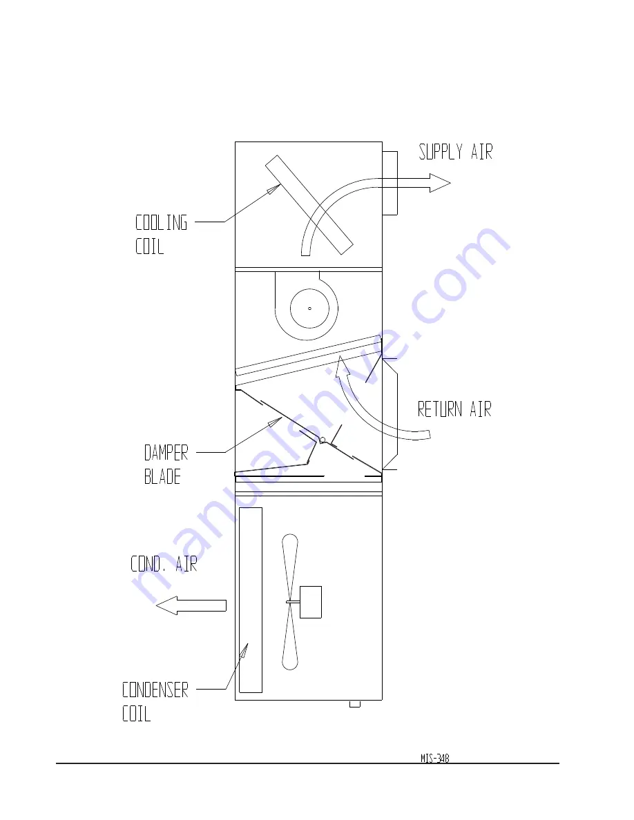
A call for cooling cycles the compressor, and dampers remain in the ventilation mode. On loss of blower operation, CRV closes fully. See Figure 8.
FIGURE 8
CALL FOR COOLING OPERATION
Page 1: ...EL CRVMP 5 For Use with Bard 3 through 5 Ton WA S Series Wall Mount Air Conditioners INSTALLATION INSTRUCTIONS Manual 2100 457D Supersedes 2100 457C File Volume III Tab 19 Date 01 24 14 Bard Manufactu...
Page 2: ...igures Figure 1 Removal of Exterior Panels 4 Figure 2 Remove Air Filter Exhaust Cover Plate 5 Figure 3 Install Ventilator 6 Figure 4 Step Control Installation 8 Figure 5 Damper Control Board 9 Figure...
Page 3: ...eived and that there is no visible damage Note any shortages or damage on all copies of the freight bill The receiving party must contact the last carrier immediately preferably in writing requesting...
Page 4: ...embly which includes the integral ventilator with attached electrical harness step control assembly and miscellaneous hardware WARNING Open and lock unit disconnect switch before installing this acces...
Page 5: ...00 457D Page 5 of 16 FIGURE 2 REMOVE AIR FILTER AND EXHAUST COVER PLATE 3 Remove and save existing unit air filter and screws from front center grille See Figure 2 4 Remove and discard the exhaust cov...
Page 6: ...ntilator into the unit to the far left side clearing the right filter bracket Once the ventilator is fully inserted slide the ventilator to the right until it is tight against the back of the control...
Page 7: ...he control panel through the wire looms and route them into the low voltage box through the bushing See Figure 4 Make connections following the wiring diagram enclosed in Literature Assembly or on ven...
Page 8: ...t damper blade for required ventilation See next section 16 Replace mist eliminator filter Be sure that it is installed with the drain holes to the bottom 17 Remove blank off plate or barometric fresh...
Page 9: ...TENTIOMETER FOR STAGE 1 HEATING OR COOLING DAMPER POSITION G AND Y1 CONTROL SIGNALS FOR STAGE 2 HEATING OR COOLING DAMPER POSITION G Y1 AND Y2 CONTROL SIGNALS R3 ADJUSTMENT POTENTIOMETER R1 ADJUSTMENT...
Page 10: ...See Figure 5 C Using a small screwdriver adjust potentiometer until damper position aligns with numerical location on the label interior of the sheet metal damper assembly 2 Set the damper position fo...
Page 11: ...Ventilation Airflow CFM Vent Position WA3S Ventilation Airflow Stage 2 Operation Blower Only Stage 1 Operation 0 100 200 300 400 500 600 700 800 900 1000 0 2 5 5 7 5 10 12 5 15 17 5 20 22 5 25 27 5 30...
Page 12: ...Page 12 of 16 0 100 200 300 400 500 600 700 800 900 1000 0 2 5 5 7 5 10 12 5 15 17 5 20 22 5 25 27 5 30 Ventilation Airflow CFM Vent Position WA5S Ventilation Airflow Stage 2 Operation Stage 1 Operat...
Page 13: ...rd rate to ASHRAE standards BASIC INSTALLATION 1 Make sure power is turned off to the unit 2 Follow steps beginning on page 2 for installation for standard control and vent assembly then proceed with...
Page 14: ...on with Controller For High Altitude Installations CAL Used for Field Calibration 1 Damper should be fully closed at 700 ppm if not Potentiometer R7 can be adjusted clockwise CW to close it If it is f...
Page 15: ...ir damper built in with positive closed position Provides exhaust air capability to prevent pressurization of tight buildings Actuator motor 24 volt power open spring return with built in torque limit...
Page 16: ...al 2100 457D Page 16 of 16 A call for cooling cycles the compressor and dampers remain in the ventilation mode On loss of blower operation CRV closes fully See Figure 8 FIGURE 8 CALL FOR COOLING OPERA...