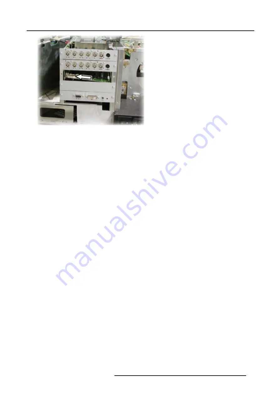
3. DVI input (re)placement
Image 3-32
Caution:
Tightening the screw too much can damage the connectors !
Tip:
When tightening the screw the board will be “pulled” into the connectors hereby lifting and positioning it horizontally.
3. Mount and tighten the side screw (of slot 3 in this case) on the lens side.
4. Mount and fix the front DVI plate and tighten the screws.
Note:
first tighten the 2 on the side (are pre-mounted to fix the dummy plate) and then the 4 middle screws (delivered in the kit).
R5976887 DVI INPUT KIT FOR ICON 29/03/2006
19
Summary of Contents for R9843030
Page 1: ...DVI input Kit for iCon Installation Manual R9843030 R5976887 00 29 03 2006...
Page 4: ......
Page 6: ...Table of contents 2 R5976887 DVI INPUT KIT FOR ICON 29 03 2006...
Page 8: ...1 Safety 4 R5976887 DVI INPUT KIT FOR ICON 29 03 2006...
Page 10: ...2 Kit description Image 2 3 6 R5976887 DVI INPUT KIT FOR ICON 29 03 2006...


