background image

8. Maintenance

Image 8-29
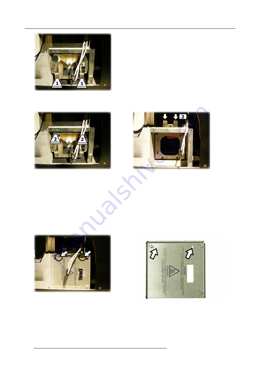
Lamp inserting:

fi

rmly push the bottom side

fi

rst

5. Then

fi

rmly push the top side of the lamp, while carefully pushing the lamp locking handle down

Image 8-30
Lamp inserting:

fi

rmly push the top side...

Image 8-31
Lamp inserting: ... while carefully pushing down the lamp locking handle

6. Check the

fi

xation of the lamp by trying to move it left-right and up-down: it should not move!

8.4.5

Installing the lamp door

Necessary tools

Torx screwdriver T10

How to install the lamp door?

1. Put the lamp door in the right position

Tip:

The two positioning points must coincide with the two positioning holes

Image 8-32
Lamp door: positioning points & holes

Image 8-33
Lamp door: positioning holes

2. Tighten the three screws

162

R59770198 BARCO SIM 7D 13/02/2013

Summary of Contents for R92112071

Page 1: ...Barco SIM 7D User Guide R92112071 R92112072 R92112073 R59770198 10 13 02 2013 ...

Page 2: ...Barco nv Advanced Visualization Systems Noordlaan 5 B 8520 Kuurne Phone 32 56 36 82 11 Fax 32 56 36 84 86 Support www barco com esupport Visit us at the web www barco com Printed in Belgium ...

Page 3: ...tems from other types of waste and recycle them responsibly to promote the sustainable reuse of material resources For more information about recycling of this product please contact your local city office or your municipal waste disposal service For details please visit the Barco website at http www barco com en AboutBarco weee Disposal of batteries in the product This product contains batteries ...

Page 4: ...guaranteed in writing or due to the intent or gross negligence or part of Barco If the purchaser or a third party carries out modifications or repairs on goods delivered by Barco or if the goods are handled incorrectly in particular if the systems are commissioned operated incorrectly or if after the transfer of risks the goods are subject to influences not agreed upon in the contract all guarante...

Page 5: ...w 32 4 8 2 Infrared receivers 34 5 Setup 37 5 1 Warranty continuous mode automatic shutdown mode 37 5 2 Powering the SIM 7 projector 37 5 3 Setting the RCU address 38 5 4 Starting the projector 39 5 5 Setting the projector address only if necessary 40 5 6 Setting up the orientation 41 5 7 Lens adjustments 41 5 7 1 Locking the lens holder rugged option 41 5 7 2 Locking unlocking the zoom ring and t...

Page 6: ... 2 Identification 96 7 8 Display setup 97 7 8 1 Textbox 97 7 8 2 Menu bar position 97 7 8 3 Slider box position 98 7 8 4 Sync variance limit 99 7 8 5 Soft edge 100 7 8 5 1 Introduction 100 7 8 5 2 Accessing the Soft edge menu 102 7 8 5 3 Soft edge edit 102 7 8 5 3 1 The soft edge edit wizard 102 7 8 5 3 2 The soft edge edit modes 103 7 8 5 3 3 Creating editing a soft edge 105 7 8 5 3 4 Alpha plane...

Page 7: ...ng the exterior of the projector 151 8 3 Air filter replacement 152 8 3 1 Removing the x cube filter 153 8 3 2 Installing the x cube filter 154 8 3 3 Removing the electronics filter 155 8 3 4 Installing the electronics filter 157 8 4 Lamp replacement 158 8 4 1 Removing the lamp cover 159 8 4 2 Removing the lamp door 159 8 4 3 Removing the lamp 160 8 4 4 Installing the lamp 161 8 4 5 Installing the...

Page 8: ...Table of contents 4 R59770198 BARCO SIM 7D 13 02 2013 ...

Page 9: ...jection parameters in order to get the best image reproduction 3 Getting started Start the projector for daily use 4 Advanced Advanced operation and setup using the remote control and the projector s OSD 5 Service and Maintenance Maintenance operations on the projector CAUTION For the latest version of the product manuals see http www barco com Related documentation Several advanced adjustments ar...

Page 10: ...1 Introduction 6 R59770198 BARCO SIM 7D 13 02 2013 ...

Page 11: ...added to the packaging to keep it dry Do not open these disposable bags Image 2 1 Silicagel Foam The projector is packed in a cardboard box To provide protection during transportation the projector is surrounded with foam The package is secured with banding and fastening clips Lens delivered The projection lens delivered with the projector will vary depending on the product number ordered and is p...

Page 12: ...eplacement of the projection lens How to unpack the projector 1 Release the cord straps PULL TO OPEN Image 2 2 2 Remove the assembly from the pallet 3 Open the outer cardboard box 4 Remove the two smaller box which contains User guide and Safety manual RCU batteries power cords projection lens 5 Remove the foam parts 6 Open the inner cardboard box 7 Remove the foam parts 8 Lift the projector out o...

Page 13: ...ens small box Image 2 3 Unpacking the cardboard box exploded view Retain the original shipping cardboard boxes and packing material It will be needed if you ever have to ship the projector For maximum protection repack your projector as it was packed at the factory R59770198 BARCO SIM 7D 13 02 2013 9 ...

Page 14: ...2 Packaging 10 R59770198 BARCO SIM 7D 13 02 2013 ...

Page 15: ...e size ambient light level projector placement and type of screen to use are critical to the optimum use of the projection system Temperature conditions Temperature range during operation Min ambient temperature 0 C or 32 F Max ambient temperature 40 C or 104 F The projector will not operate if ambient air temperature falls outside this range 0 C 40 C or 32 F 104 F Temperature range in non operati...

Page 16: ...y unwanted light or reflection Some rules can be useful switch off any light source during projection reflection should be avoided e g by using dark wall ceiling and floor color windows must be fully darkened only aimed spotlight should be used to illuminate small areas if really needed It is important to carefully consider lighting conditions Dedicated engineers or scientists can point out the ne...

Page 17: ...ctor Projector tilt RCU battery installation Lens installation Projector configuration Connections Controls 4 1 Dimensions Projector dimensions and weight Dimensions are given in mm and inch 1 inch 25 4 mm Weight without lens approximately 27 5 kg 60 6 lbs R59770198 BARCO SIM 7D 13 02 2013 13 ...

Page 18: ...xation points To fix the projector to its support three bolts can be screwed into the threaded holes at the bottom of the projector The bolts must meet the following specifications bolt type M8x1 25 strength class 8 8 or higher preferred bolt length bolt head not included 25 mm bolt length 30 mm mounting torque range 20 Nm 177 lbf in torque 23 Nm 205 lbf in 14 R59770198 BARCO SIM 7D 13 02 2013 ...

Page 19: ...rojector tilt range will cause lamp flicker or even lamp explosion Tilt range The tilt range of the projector is restricted by the tilt range of the lamp The drawings below show the maximal tilt range in both senses 20 20 Image 4 3 Projector tilt range R59770198 BARCO SIM 7D 13 02 2013 15 ...

Page 20: ...very the batteries can be found in a separated bag attached to the remote control unit Before using your remote control install the batteries first How to install the batteries in the remote control 1 Push the battery cover tab with the fingernail a little backwards 1 and pull at the same time the cover upwards 2 1 2 Image 4 5 2 Insert the two AA size batteries making sure the polarities match the...

Page 21: ...alent type recommended by the manufacturer Disposal of used batteries must be done according to the manufacturer s instruction 4 5 Lens installation Overview Lens range Lens formulas Shift capabilities Installing the lens and adjusting the Scheimpflug Connecting the lens Lens Data 4 5 1 Lens range Overview table Lens Partnumber QSD 0 8 1 R9849990 QSD 1 0 1 4 1 R9849975 QSD 1 4 2 0 1 R9849980 See t...

Page 22: ...Wide Angle PDmin 0 0299 1 026 x SW 0 0047 SW PDmin 1 177165 1 026 x SW 7 285015 SW QSD 1 0 1 4 1 TP Telephoto PDmax 0 0341 1 434 x SW 0 0030 SW PDmax 1 34252 1 434 x SW 4 650009 SW WA Wide Angle PDmin 0 0858 1 471 x SW 0 0077 SW PDmin 3 37795 1 471 x SW 11 93502 SW QSD 1 4 2 0 1 TP Telephoto PDmax 0 0013 2 031 x SW 0 0606 SW PDmax 0 05118 2 031 x SW 93 9302 SW 4 5 3 Shift capabilities Overview Len...

Page 23: ... 20 20 20 70 Image 4 11 Lens shift range The best image quality is obtained in nominal lens position i e 0 shift Shifting the image to the limit of its range starts introducing some falloff The exact range in the area indicated by the red dashed line depends on lens type and application R59770198 BARCO SIM 7D 13 02 2013 19 ...

Page 24: ...the lens and adjusting the Scheimpflug WARNING In case of a projector with NVG option do not insert your fingers in the lens holder if the lens is removed They could get hit by the smearing reduction wheel Image 4 14 CAUTION Make sure that the projection lens and the interpolation lens are a matched set Replacing any one of these units requires the replacement of the other Each of the lenses have ...

Page 25: ...o the lens flange See image 4 15 and image 4 16 Tip Make sure the bolts do not completely go through the flange 2 Fix a nut M4 to the Allen bolts Do not tighten yet Image 4 15 Screws to lock the lens scheimpflug settings left side Image 4 16 Screws to lock the lens scheimpflug settings right side How to mount the lens on the projector and adjust the Scheimpflug 1 Remove the top lens cover 6 screws...

Page 26: ...lock nuts and washers from the lens holder studs but leave the springs on the lens holder studs Image 4 19 Lens scheimpflug springs 4 Slide the lens over the 3 studs Image 4 20 Lens positioned 5 Put a washer and a lock nut on each stud 22 R59770198 BARCO SIM 7D 13 02 2013 ...

Page 27: ...s and nuts 9 Secure the smaller Allen bolts M4 by tightening the nuts see 2 on image 4 22 to the lens flange 10 Install the bottom lens cover 11 Install the top lens cover 4 5 5 Connecting the lens What must be done The lens must be connected to the projector to allow the control of the Zoom and Focus and to allow data communication for the aperture control Connecting or disconnecting the lens whi...

Page 28: ...the projector are fitted with a non volatile memory holding the lens serial number and dynamic aperture look up tables These look up tables allow to determine the exact opening position in function of the desired light output determined for example by the Time of Day setting To make this possible the lens is connected to the front of the projector chassis through a 16 wire cable Connection The con...

Page 29: ... 4 Image 4 26 Projector configurations 4 7 Connections Overview Power connection Signal connections Communications 4 7 1 Power connection Voltage Ampere Frequency rating Projector type Voltage range AC Current Frequency SIM 7 100 240 V single phase 6 3 A 50 60 Hz How to connect the power 1 Use the supplied power cord to connect the projector to the power outlet 2 Plug the female power connector in...

Page 30: ...locking spring OPEN CLOSED Image 4 28 CAUTION To prevent damage to the projector always ensure that the locking spring is well engaged 4 7 2 Signal connections Overview The input section Input specifications Connecting a DVI source Source specification 26 R59770198 BARCO SIM 7D 13 02 2013 ...

Page 31: ...ng to one frustum D15 computer input not supported communication layer 2x RJ45 LAN1 and LAN2 Each LAN input is connected to one frustum image processor PMP or Pixel Map Processor Image 4 29 Projector left side view Image 4 30 Input section 4 7 2 2 Input specifications DVI input board This board includes DVI single link digital input Even though the connector is of the DVI I type the analog part is...

Page 32: ...on What are the required source specifications In order to allow a perfect display of the 2 frustum images i e a perfect overlap and perfect alignment with respect to the display area the source must meet the following specifications Source resolution per frustum 1184 horizontal x 1536 vertical pixels Vertical refresh rate 60 Hz How will the total image be formed The total image on projector level...

Page 33: ...nnel display system The warping and the soft edge settings are performed via Barco XRacu See the dedicated system manual for more information 4 7 3 Communications Overview The LAN inputs Connecting to the network Network settings 4 7 3 1 The LAN inputs Network communication The projector allows the connection to a network This can be a local or a small dedicated network This way the projector can ...

Page 34: ...e the ethernet communication can be done with each board separately Each input is connected to one of the 2 image processors which are both addressed separately To allow the communication with both image processors it is advised to use a Hub or Switch it is however required to have a DHCP and DNS server present in the LAN To send commands to the projector connection must be established to port 540...

Page 35: ... Installation menu 4 Push the cursor key or to highlight Network settings and press ENTER to select Image 4 34 A dialog box will be displayed Image 4 35 5 Push the cursor key or to highlight the desired parameter 6 Use the cursor key or the numeric keys on the RCU or the local keypad to edit and change the values 7 Press Apply settings to apply the changes R59770198 BARCO SIM 7D 13 02 2013 31 ...

Page 36: ...for the master PMP left frustum consists out of an S followed by the serial number of the projector and followed by A By default the Hostname for the slave PMP right frustum consists out of an S followed by the serial number of the projector and followed by B 4 8 Controls 4 8 1 Controls overview RCU The following table gives an overview of the different keys 32 R59770198 BARCO SIM 7D 13 02 2013 ...

Page 37: ... switch off the projector without switching off the power switch Attention Switching to Standby When the projector is running and you want to go to standby press the standby key for 2 seconds 7 MUTE to interrupt the sound reproduction audio optional 8 AUTOIMAGE Auto image to center the image on the active LCD surface 9 Digit buttons direct input selection 9b SOURCE button the Source Selection menu...

Page 38: ...0 PIP ADJUST allows to select a PiP window and change its configuration on screen 21 RC operating indication lights up when a button on the remote control is pressed This is a visual indicator to check the operation of the remote control 22 IR receiver IR receiver Table 4 6 ordernumber RCU R763794K Local keypad Image 4 38 Local keypad location Image 4 39 4 8 2 Infrared receivers Location of the in...

Page 39: ...4 Installation Image 4 40 Location of the IR receivers R59770198 BARCO SIM 7D 13 02 2013 35 ...

Page 40: ...4 Installation 36 R59770198 BARCO SIM 7D 13 02 2013 ...

Page 41: ...e projector will display a warning on the projected image after 24 hours of continuous active mode saying that the projector will automatically switch off in four minutes A counter will count back from 4 minutes to zero At that time the projector will switch off In this mode warranty of the lamp remains Continuous mode If continuous mode is selected the projector can reside in active state for mor...

Page 42: ...range 0 9 To know the address of the projector one can visualize it in projection mode on screen as well as in standby mode shown with the LED s on top cover of the projector For more info on addresses see the appendix At this stage the image projected may happen to be upside down or mirrored this can be set in the Installation menu under Projector orientation see further setting up the projector ...

Page 43: ...e room 2 Enter the same address with the digit buttons within 5 seconds after pushing the address key The projector can now be controlled with the RCU For example if the projector address is 3 then press 3 on the RCU to set the RCU s address to match the projector s address Common address Projector address Beside the projector address the projector disposes also of a Common address which can be se...

Page 44: ...can be programmed Projector address address defined by the user may be from 0 to 255 0 9 is used for RCU communication Common address address may be 0 or 1 How to change the projector s address 1 Press MENU to activate the Tool bar 2 Press to select the Installation 3 Press to Pull down the Installation menu 4 Use or to select Projector address Image 5 6 5 Press ENTER A dialog box appears on the s...

Page 45: ...on is adapted and a bullet shows the active configuration When changing the orientation from table to ceiling or vice versa the Smearing reduction must also be set accordingly scan direction in the remote user interface See the dedicated System manual for more infor mation 5 7 Lens adjustments Overview Locking the lens holder rugged option Locking unlocking the zoom ring and the focus ring of the ...

Page 46: ... the top lens cover Image 5 9 Lens top cover fixing screws 3 Slide both fixation blocks for the horizontal shift away from each other until they hit the lens holder frame Image 5 10 Horizontal shift free Image 5 11 Horizontal shift blocked 4 Fix these blocks by tightening the front bolts Image 5 12 Fixation screws for horizontal lens shift locking system 42 R59770198 BARCO SIM 7D 13 02 2013 ...

Page 47: ...ay occur In order to avoid this the zoom ring and the focus ring of the lens can be locked mechanically on some of the lenses Depending on the lens article number the zoom and focus locking system will be available or not CAUTION Make sure to unlock the zoom and focus ring before adjusting the zoom focus Necessary tools No tools How to lock the zoom ring and the focus ring of the lens Both zoom ri...

Page 48: ...g system 2 Now the zoom and focus can be adjusted 5 7 3 Back focal length adjustment BFL Back Focal Length What can be done The position of the projector lens in relation to the interpolation lens can be adjusted The lens can be shifted towards or away from the projector chassis By doing so the back focal length is adjusted and the focus is set to an optimal value This adjustment will allow to ben...

Page 49: ... not allow optimal focus throughout the full zoom range Necessary tools BFL adjustment tool Allen key 2 5 mm hexagonal key How to adjust 1 Loosen the 4 screws along the outline of the lens top bottom left right Tip Only loosen these screws a bit Just enough to allow the lens to be shifted forward and backward R59770198 BARCO SIM 7D 13 02 2013 45 ...

Page 50: ... in the adjustment hole Image 5 19 Back focal length adjustment tool 3 Zoom the lens to wide position 4 Focus the image on the screen using the BFL tool Image 5 20 Back focal length adjustment range 5 Zoom the lens to tele position 6 Focus the image on the screen using the remote control 46 R59770198 BARCO SIM 7D 13 02 2013 ...

Page 51: ...nlock the focus ring and the zoom ring before adjusting the zoom or focus of the lens CAUTION In case of a projector with rugged option make sure to unlock the lens holder before shifting it up down or left right How to adjust the lens using the direct keys on the RCU 1 Use one of the following keys on the RCU Lens shift or to shift down or up Lens zoom or to zoom out or in Lens focus or to adjust...

Page 52: ...erform the desired action 9 0 EN T ER M EN U B A C K D I G I Z O O M PH A SE P A U SE PI P L O G O Image 5 25 How to adjust the zoom focus using the OSD 1 Press MENU to activate the Tool bar 2 Press or to select the Installation 3 Press to Pull down the Installation menu 4 Use or to select Lens adjustments 48 R59770198 BARCO SIM 7D 13 02 2013 ...

Page 53: ... 28 The use of a sheet of paper held in front of the screen can be useful to determine the focus plane position for best focus Unsharp corners in the image can be adjusted with the Scheimpflug adjustment 3 adjustment screws on the lens holder see the Lens installation section Before adjusting the lens focus insure that the Back Focal Length is correctly adjusted Back focal length adjustment page 4...

Page 54: ...5 Setup 50 R59770198 BARCO SIM 7D 13 02 2013 ...

Page 55: ...t a source using the RCU A source must be connected and available to be able to display it 1 Press one of the following keys to display a source press 2 on the RCU to display the source connected to the D15 connector press 5 on the RCU to display the source to the DVI connector press 8 on the RCU to hide any source AUT AUTO IMAGE O IMAGE PC PC RGB RGB VIDEO VIDEO Fire W Fire Wire ire DVI DVI IQ PC...

Page 56: ...d to switch it to standby to save energy or it can be fully powered off after the cooling cycle The advantage of standby mode compared to power off mode is the time to get it back to active state i e lamp on After switching the projector to standby the lamp is switched off and the cooling cycle is started two minutes Do not power off the projector during the cooling cycle since doing so reduces th...

Page 57: ...trol 1 Press ENTER to activate the input field Image 7 1 2 Key in the desired value Entering numeric values using the arrow keys on the remote control 1 Press ENTER to activate the input field 2 Press or to select the digit to be changed Image 7 2 3 Press or to increase or decrease the value Entering numeric values using the arrow keys on the local keypad 1 Press ENTER to activate the input field ...

Page 58: ...1 and a DVI input board on the second layer L2 The native resolution of the projector panels is 2048 x 1536 with an aspect ratio of 4 3 7 2 2 Selecting the L1 DVI source What can be done The L1 DVI source is one out of the two sources that will make up the full dual frustum image The dual frustum image being made up by L1 DVI and L2 DVI Selecting L1 DVI while L2 DVI is also connected and available...

Page 59: ...on menu 3 Use or to select L2 DVI Image 7 4 4 Press ENTER to confirm your choice A bullet indicates the selected source which now appears on the screen Adjustments on the L2 DVI source The digital nature of this signal eliminates the need of adjustments 7 2 4 Selecting a PC source L1 PC L2 PC PC source L1 PC and L2 PC are not supported 7 3 Image Overview Introduction Image settings Time of Day TOD...

Page 60: ... 2 Press to select the Image item 3 Press to Pull down the Image menu 4 Use or to select settings 5 Press to pull down the menu 6 Use or to select Contrast 7 Press ENTER On the screen appears now a slider box Image 7 6 8 Use or the numeric keys on the remote or the keypad to change the contrast 7 3 2 2 Setting the Brightness Brightness adjustment Adjusting the brightness will affect the dark areas...

Page 61: ...the Tool bar 2 Press to select the Image item 3 Press to Pull down the Image menu 4 Use or to select settings 5 Press to pull down the menu 6 Use or to select Gamma 7 Press ENTER On the screen appears now a slider box Image 7 8 8 Use or the numeric keys on the remote or the keypad to change the Gamma 7 3 2 4 Phase RGB signals only Phase adjustment A bad phase adjustment will result in bad transiti...

Page 62: ... Enhanced Contrast Ratio 2 When the ECR is at its minimum value the CCD Constant Contrast Dimmer starts further dimming the light output until it is 0 Motorized dimming at different stages in the projector insures a better dynamic behavior through ECR Ex tended Contrast Ratio and CCD Constant Contrast Dimming by enabling the possibility to adjust the light output level of the projector and preserv...

Page 63: ...lar file to be used for the display of a particular source In this case the user should load the desired file from the image files menu The load file option will allow the user to choose between several files corresponding more or less to the active source specifications In normal operation the file selection load will be done automatically by Auto Image How to load a file 1 Press MENU to activate...

Page 64: ...s not correct after Auto Image or after selecting the best fitting file go to the Edit menu select the active file and change the settings 7 4 2 Auto Image What can be done Auto Image creates the best suited image file for the connected source It calculates measures several source parameters Total pixels per line Start pixel Phase Contrast Brightness levels Auto Image only works for data images Th...

Page 65: ...image in the window may move and change in aspect during the AutoImage process Auto Image can also be launched via the RCU with the dedicated AutoImage key 7 4 3 Edit file What can be done with the Edit file menu The Edit file menu makes it possible to change the settings of the file according to the real settings of the connected source Consult the source specifications before entering the data I...

Page 66: ...pdated Advanced settings for Analog Data sources e g RGB HS VS The advanced button enables the advanced settings for analog data sources Image 7 17 Color space allows to select between 5 different color spaces RGB ITU_BT_709 SMPTE_240M ITU_BT_601 EBU Clamp position allows to set the clamp pulse position in the clamping circuit Clamp width allows to set the width of clamp pulse in the clamping circ...

Page 67: ...enu Image 7 19 7 4 4 Save as create a custom file Creating a custom file When the loaded file is a standard file there is a possibility of saving it as a custom file creating a custom file this is done with the save as function The saved file will always be a custom file saved in the custom directory For sources that are often used a custom file should be created This custom file will then be load...

Page 68: ... displayed Use or or the numeric keys on the remote or the keypad to edit and change the values confirm with ENTER Image 7 23 7 4 6 Copy Copy a file The copy function allows to copy a file standard or custom to a custom file to the custom directory How to copy a file 1 Press MENU to activate the Tool bar 2 Press to select the Image files item 3 Press to Pull down the Image files menu 4 Use or to s...

Page 69: ...ile name is copied in the edit field 8 Use the keys on the remote to change the name of the destination file 7 4 7 Delete How to delete a file 1 Press MENU to activate the Tool bar 2 Press to select the Image files item 3 Press to Pull down the Image files menu 4 Use or to select delete Image 7 26 R59770198 BARCO SIM 7D 13 02 2013 65 ...

Page 70: ...indicated in the menu How to force a file to be loaded 1 Press MENU to activate the Tool bar 2 Press to select the Image files item 3 Press to Pull down the Image files menu 4 Use or to select Forced file load 5 Press to open the menu 6 Use or to select the desired layer for example Layer 1 7 Press to open the menu 8 Use or to select the desired input Image 7 28 Note Inputs that are not hardware c...

Page 71: ...that can be imagined by pre distorting the image inside the projector a correct geometry can be achieved on curved screens without requiring additional computational power on the IG s side 7 5 2 Geometry files Description A geometry file contains the geometry corrections The projector s memory contains a list of files created for demo purposes e g to demonstrate the warping capabilities of the pro...

Page 72: ...t submenu This allows the adjustment of the left and right frustum indepen dently from each other How to access the Geometry menu 1 Press MENU to activate the Tool bar 2 Press to select Geometry 3 Press to Pull down the Geometry menu 4 Use or to select the Right or Left submenu Note The Right menu contains the same items as the Left submenu 5 Press to open the menu Image 7 30 7 5 4 Geometry distor...

Page 73: ... frustum is divided in 33x33 regions Each frustum will be adjusted separately Both distortions must however be matched so as to make up one full image and to insure the best overlap area Blanked Blanked RESULT OVERLAP Image 7 32 Total image after warping and soft edge Modes and Levels The geometry adjustment is divided in 6 groups or modes 2x2 3x3 5x5 9x9 17x17 33x33 R59770198 BARCO SIM 7D 13 02 2...

Page 74: ... 17 21 21 20 21 19 21 20 21 18 21 20 21 19 21 21 20 21 21 21 21 21 21 19 20 18 20 19 20 20 21 17 21 21 20 21 19 21 20 21 18 21 20 21 19 21 21 20 21 21 21 21 21 21 19 20 18 20 19 20 20 21 17 21 21 20 21 19 21 20 21 18 21 20 21 19 21 21 20 21 21 21 21 21 21 19 20 18 20 19 20 20 21 17 21 21 20 21 19 21 20 21 18 21 20 21 19 21 21 20 21 21 21 21 21 21 19 20 18 20 19 20 20 21 17 21 21 20 21 19 21 20 21 ...

Page 75: ...s hierarchy the 2x2 points Adjusting points on level 1 will affect level 2 till 21 At the bottom of the structure we find the 33x33 points adjustment adjusting grid points on level 21 will not affect any other points these are called local points 7 5 5 Load How to load a geometry file for the left frustum 1 Press MENU to activate the Tool bar 2 Press to select Geometry 3 Press to Pull down the Geo...

Page 76: ..._Distortion file The file is loaded and the geometry settings are adapted The procedure is similar for the Right frustum 7 5 6 Edit Overview Accessing the Geometry Edit menu Geometry Edit wizard Geometry Edit Modes Editing a geometry file Shift Adjustment Transport Delay Geometry Reset The images below show adjustments performed on a hatch pattern generated internally by the projector see internal...

Page 77: ...elect the Right or Left submenu 5 Press to open the menu 6 Press or to select Edit 7 Press to open the Edit menu Image 7 37 7 5 6 2 Geometry Edit wizard The geometry wizard When entering the Edit mode the Edit dialog box is displayed When selecting a point in a certain adjustment a blue dotted box is placed around the selected grid point indicating the interaction zone R59770198 BARCO SIM 7D 13 02...

Page 78: ...7 Advanced Image 7 38 Interaction and selection boxes Image 7 39 Unaffected regions 74 R59770198 BARCO SIM 7D 13 02 2013 ...

Page 79: ...ill be between 0 and 32 steps of 32 PixelX this slider box adjusts the new position of the point along the x axis in a 2x2 adjustment PixelX will be between 0 and 32 steps of 0 1 pixels PixelY this slider box adjusts the new position of the point along the y axis in a 2x2 adjustment PixelY will be between 0 and 32 steps of 0 1 pixels edit box PixelX this edit box allows to edit the position of the...

Page 80: ...7 Advanced Image 7 41 Image 7 42 Image 7 43 76 R59770198 BARCO SIM 7D 13 02 2013 ...

Page 81: ... lowest level points and end with the highest level zones see Geometry distortions level hierarchy A 3x3 mode adjustment gives the following new points to be adjusted the 4 points of the 2x2 mode being already adjusted they are therefore left out of the grid Note that in this mode 2 levels are involved the level 2 and the level 3 A 5x5 mode adjustment gives the following new points to be adjusted ...

Page 82: ...vanced The column is adapted to 32 Image 7 45 2 Press to select the next adjustment point The row is adapted to 32 Image 7 46 3 Press to select the next adjustment point 78 R59770198 BARCO SIM 7D 13 02 2013 ...

Page 83: ...t the value of PixelsY The image is distorted along the X axis Notice the unaffected regions The adjustment is done in small steps Adjusting for instance from 0 to 100 using the Adjust mode is not the ideal method The use of the Edit and Change mode is more appropriate How to adjust using the Edit and Change mode Adjusting point row 0 column 0 by 100 pixels along the x axis in the 2x2 mode 1 Press...

Page 84: ... to fill in the desired value The image is distorted along the X axis Notice the unaffected regions 7 5 6 5 Shift Adjustment What can be done with the Shift adjustment With the Shift adjustment it is possible to shift the whole image This is considered as a displacement of the 4 corner points of the 2x2 mode The same dialog box is used as for the geometry edit How to use the Shift adjustment 1 Sta...

Page 85: ... selected by default instead of the Select mode for the other geometry adjustments 4 Press ENTER to go to the Edit Mode The Edit mode is selected Image 7 51 5 Use and to select the PixelsX edit box The PixelsX edit box is focused Image 7 52 6 Press ENTER R59770198 BARCO SIM 7D 13 02 2013 81 ...

Page 86: ...me C frame D z z transport delay or TDR signal coming from PMP 1st step signal processing in PMP 2nd step Image 7 54 Transport delay During this delay all image information is stored in a memory block on the PMP A Transport Delay set to the maximum value of 1023 corresponds with a delay of 16 ms What can be done with the Transport Delay The data flow of any frame starts with pixel 1 of line 1 of t...

Page 87: ...distorted images are needed extremely curved screens A delay set too short may introduce clipping phenomenons in the image How to set Transport Delay to manual or automatic 1 Start up the Geometry Edit menu 2 Push the cursor key or to highlight Transport Delay and press ENTER to select Image 7 56 The Transport Delay dialog box will be displayed Image 7 57 3 Push the cursor key or to select the rad...

Page 88: ...t Delay Range can be set from 0 to 1023 Tip When the transport delay needs to be adjusted In a multi channel setup first adjust the transport delay of all projectors one by one leave the projector with the maximum value then set all other projectors to this maximum value 3 Press BACK to return to the Geometry Edit menu 7 5 6 7 Geometry Reset Overview Reset all levels Restore to a level 7 5 6 7 1 R...

Page 89: ...a jump 5 Press BACK to return to the Geometry Edit menu 7 5 6 7 2 Restore to a level What can be done Restore to a level means that all the higher level geometry corrections are reset all geometry correction values are set to 0 The correction values of the level and all the lower levels are kept R59770198 BARCO SIM 7D 13 02 2013 85 ...

Page 90: ...e restoring to a 9x9 level How to restore to a level 1 Start the Geometry Edit menu 2 Push or to select Reset 3 Push the key to pull down the menu 4 Push or to highlight the desired level to restore Restore to 86 R59770198 BARCO SIM 7D 13 02 2013 ...

Page 91: ...ns this will be noticed in the image by a more or less accentuated jump 5 Press BACK to return to the Geometry Edit menu 7 5 7 Rename a Geometry File How to rename a geometry file 1 Start up the Geometry menu 2 Press to select Rename Image 7 62 3 Press ENTER R59770198 BARCO SIM 7D 13 02 2013 87 ...

Page 92: ... use or to browse through the characters 5 Press ENTER The file is renamed 6 Press BACK to return to the Geometry Edit menu 7 5 8 Copy a Geometry File How to Copy a Geometry File 1 Start up the Geometry menu 2 Press to select Copy Image 7 64 3 Press ENTER A dialog box is displayed 88 R59770198 BARCO SIM 7D 13 02 2013 ...

Page 93: ...keys on the RCU or the local keypad to edit and change the values confirm with ENTER 7 Press BACK to return to the Geometry Edit menu 7 5 9 Delete a Geometry File How to Delete a Geometry File 1 Start up the Geometry menu 2 Press to select Delete Image 7 66 3 Press ENTER A dialog box is displayed Image 7 67 R59770198 BARCO SIM 7D 13 02 2013 89 ...

Page 94: ...p power mode CLO Mode 7 6 1 Runtimes Typical runtime The lamp for this projector has its typical runtime It must be replaced when the runtime is reached When this runtime is reached a warning will be displayed on the projected image and the warranty will have expired The warning message can be removed from the image by pressing the Back key on the RCU but it will pop up again every time the projec...

Page 95: ...u the lamp runtime warning will only be displayed at the next startup of the projector not during a session Enabling or disabling TextBox does not affect the display of the lamp runtime warning How to set the lamp runtime warning 1 Press MENU to activate the Tool bar 2 Press to select the Lamps item 3 Press to pull down the Lamps menu 4 Use or to select Runtime warning Image 7 71 5 Press ENTER A d...

Page 96: ...runtime Reset the lamp runtime whenever you replace a lamp WARNING Lamp runtime reset as well as the lamp replacement can only be done by a Barco authorized technician How to reset the lamp runtime 1 Press MENU to activate the Tool bar 2 Press to select the Lampsitem 3 Press to pull down the Lamps menu 4 Use or to select Reset runtime Image 7 75 92 R59770198 BARCO SIM 7D 13 02 2013 ...

Page 97: ... Economic the lamp power is reduced to 250W generation 2 lamp and the light output is decreasing accordingly CAUTION Switching between Normal lamp mode and Economic lamp mode can only be done 6 times and only within the first 100 hours of the lamp life On each switch a dialog box indicates the actual amount of performed lamp power mode switches and asks for confirmation Once the lamp life time has...

Page 98: ...one Constant Light Output allows to force a constant light output set in the CLO Target menu of the projector over a certain period This will eliminate uncontrolled light output drop caused by natural aging of the lamp The CLO is done by automatically adjusting the Dimmer How to set the CLO On or Off 1 Press MENU to activate the Tool bar 2 Press to select the Lamps item 3 Press to pull down the La...

Page 99: ... select the Lampsitem 3 Press to pull down the Lamps menu 4 Use or to select CLO 5 Press to pull down the menu 6 Use or to select Target Image 7 80 7 Press ENTER A dialog box is displayed Image 7 81 8 Use or the numeric keys on the remote or the keypad to change the target value 7 7 General Overview Pause Identification 7 7 1 Pause Pause The Pause function allows to interrupt the image display The...

Page 100: ...ion screen The identification screen displays the projector s main characteristics The software version for the Master as well as for the Slave is displayed the first version is the master software version both versions are separated with a How to display the identification screen 1 Press MENU to activate the Tool bar 2 Press to select General 3 Press to Pull down the General menu 4 Use or to sele...

Page 101: ...Tool bar 2 Press to select the Display setup item 3 Press to Pull down the Display setup menu 4 Use or to select Textbox 5 Press to pull down the menu 6 Use or to enable ON or disable OFF the textbox Image 7 85 7 Press ENTER A white bullet shows the active setting 7 8 2 Menu bar position What can be done The menu tool bar can be centered vertically the range being from top of the screen to the mid...

Page 102: ... box function allows to display or hide the different boxes used for instance for picture settings contrast How to reposition the slider box 1 Press MENU to activate the Tool bar 2 Press to select the Display setup item 3 Press to Pull down the Display setup menu 4 Use or to select Slider box position Image 7 87 5 Press ENTER A slider box is displayed Use the 4 arrow keys to drag the box to the de...

Page 103: ...essed This will lead to a jumping image or frame tearing image distortion The best value for the sync variance limit is about 200 microseconds higher than the critical range This guarantees the display of the actual frame without distortion and with minimum delay frame B frame B frame C frame B frame D frame D x frame B frame A frame C frame B frame D frame C v x sync variance limit is critical v ...

Page 104: ... value by 100 or 200 7 8 5 Soft edge The soft edge adjustment is done on the hand held remote control unit RACU The soft edge adjustment menu on the projector should only be used for demo purposes Overview Introduction Accessing the Soft edge menu Soft edge edit Black level Blanking 7 8 5 1 Introduction What can be done When working in a multichannel setup the Soft edge feature enables an image bl...

Page 105: ...s memorized This file contains data corresponding to the shape contour of the soft edge Soft Edge Preparations To ensure proper soft edge adjustment be sure that the following adjustments are done perfectly on all projectors Geometry Color Matching Input Balance Dynacolor When projecting on a cylindrical screen the adjustments mentioned above can be done by using the projector adjustments in combi...

Page 106: ...y to pull down the menu Image 7 93 7 8 5 3 Soft edge edit Overview The soft edge edit wizard The soft edge edit modes Creating editing a soft edge Alpha planes 7 8 5 3 1 The soft edge edit wizard The geometry wizard When entering the Edit mode the Edit dialog box is displayed Description of the Edit dialog box An intuitive user interface is used to perform all the Soft edge adjustments 102 R597701...

Page 107: ...d bars can be applied on the background image during the soft edge adjustment Hierarchy level Allows to select the level of the adjustment Reset The soft edge shape is set to default settings Soft edge shape follows geometry settings the shape of the soft edge is set to 12 5 all edges are set to hard edge i e all of them are disabled Table 7 3 dialog box legend 7 8 5 3 2 The soft edge edit modes T...

Page 108: ...7 Advanced Image 7 95 Image 7 96 Image 7 97 Image 7 98 104 R59770198 BARCO SIM 7D 13 02 2013 ...

Page 109: ...um displace one point along the x axis How to start up the edit dialog box 1 Press the MENU key to activate the Tool bar 2 Push the cursor key or to highlight Display setup 3 Push the key to pull down the menu 4 Push or to select Soft edge 5 Push the key to pull down the menu 6 Push the cursor key or to highlight Edit Left Image 7 99 7 Press ENTER The soft edge dialog box will be displayed How to ...

Page 110: ...ed The item is focused Image 7 100 2 Press ENTER The internal soft edge is selected Image 7 101 How to enable the soft edges 1 Push or to select the desired Edges check box 106 R59770198 BARCO SIM 7D 13 02 2013 ...

Page 111: ...ge 7 103 3 Do the same for the other desired edges The default soft edge is applied on the selected edges How to select the source background 1 Push or to select the desired Source check box in this case we will perform the adjustment on a Full white background R59770198 BARCO SIM 7D 13 02 2013 107 ...

Page 112: ... The selected check box is checked and a full white image is displayed with the soft edges on the 4 sides Image 7 105 How to enable the adjustment guide 1 Push or to select the check box ON to enable the adjustment guide 108 R59770198 BARCO SIM 7D 13 02 2013 ...

Page 113: ... Press ENTER The selected check box is checked and the guide is displayed vertical and horizontal grey scale bars Image 7 107 How to set the hierarchy level 1 Push or to select the hierarchy level slider box R59770198 BARCO SIM 7D 13 02 2013 109 ...

Page 114: ...ENTER to confirm The selected point is displaced to the new position x 100 Y 0 8 Press BACK to exit A dialog box is displayed Press ENTER to confirm All the points of the higher levels level 2 are altered by this adjustment The points that belong to the same level level 1 remain in the same position anchors 7 8 5 3 4 Alpha planes Alpha plane specification An alpha plane is a bitmap file which will...

Page 115: ...r key or to highlight Display setup 3 Push the key to pull down the menu 4 Push or to select Soft edge 5 Push the key to pull down the menu 6 Push the cursor key or to highlight Edit Image 7 109 7 Press ENTER A dialog box will be displayed 8 Use the arrows to select the Alpha planes check box and press ENTER Image 7 110 Note It takes some time for the alpha plane to be applied R59770198 BARCO SIM ...

Page 116: ...rnal vs Alpha planes this black level adjustment can be fixed internally by using a dialog box or externally by uploading a user defined Beta plane This beta plane will contain the values for the brightness offset to be applied to the image Both methods will allow to compensate for the typical double brightness phenomenon in the soft edge zones by increasing the brightness of the rest of the image...

Page 117: ...or to select Soft edge 5 Push the key to pull down the menu 6 Push the cursor key or to highlight Black level Left or Black level Right Image 7 112 7 Press ENTER A dialog box will be displayed Black Level Internal Beta planes Planes Level 0 Image 7 113 8 Use the arrows to select the Internal check box and press ENTER Note It will take a certain time for the internal black level to be applied 9 Use...

Page 118: ...ctivate the Tool bar 2 Push the cursor key or to highlight Display setup 3 Push the key to pull down the menu 4 Push or to select Soft edge 5 Push the key to pull down the menu 6 Push the cursor key or to highlight Black level Image 7 114 7 Press ENTER A dialog box will be displayed Black Level Internal Beta planes Planes Level 0 Image 7 115 8 Use the arrows to select the Beta planes check box and...

Page 119: ...displayed 8 Uncheck all the edges 9 Adjust the soft edge as desired same procedure as above 10 Press BACK to return to the Display setup menu 7 8 6 AutoImage Setup What can be done AutoImage allows to detect automatically the characteristics of the source total pixels per line and uses this information to adapt the image to the display AutoImage can adapt the image based on following data Total pi...

Page 120: ...y fast moving objects in a displayed image Any fast moving object will look blurred or smeared along the direction of relative motion What can be done Because of its inherent characteristics LC response time liquid crystal based display devices are subject to smearing on fast mov ing images Because of its fast response time and refresh rate LCoS displays are less sensitive to smearing than other c...

Page 121: ... the image and consult a doctor if you have any of the following symptoms Convulsions Eye or muscle twitching Loss of awareness Altered vision Involuntary movements Disorien tation 7 8 7 2 Enabling Smearing reduction When activating this function a drop in light output and a noticeable flicker is inevitable How to enable the Smearing reduction if the option is installed 1 Press MENU to activate th...

Page 122: ...mage or worse smearing appearance How to adjust the Smearing reduction phase 1 Press MENU to activate the Tool bar 2 Press to select the Display setup item 3 Press to Pull down the Display setup menu 4 Use or to select Smearing reduction 5 Press to select the Smearing reduction item 6 Use to select Phase 7 Press ENTER Image 7 122 Tip Smearing reduction must be enabled to make this selection possib...

Page 123: ...te which is brightest white point that can be produced by the projector 5 different presets are available Projector white Computer 9300 K Video 6500 K Film 5400 K Broadcast 3200 K Dynacolor white These calibrated presets can be selected and will provide optimum color tracking The projector however allows the setting of a personal color temperature this is done by changing the white point coordinat...

Page 124: ... bullet shows the active setting How to set a custom color temperature 1 Change the coordinates of the white point in the Dynacolor user interface 7 8 10 Dynacolor Overview Introduction Enabling DynaColor Dynacolor adjustment Black color matching CLO TOD color tracking 7 8 10 1 Introduction What can be done DynaColor will eliminate channel to channel color variations or in case of a single project...

Page 125: ...27 The projector color gamut is defined by the triangle formed by the x y coordinates of Red Green and Blue Due to the tolerance on optical components the x y values of this color gamut of each projector will differ Image 7 128 The color gamut of each projector will differ When working with a multichannel setup these color differences between different projectors can be smooth out by matching the ...

Page 126: ...y the 3 points of intersection of the 2 separate color gamuts 0 1 0 2 0 1 0 3 0 4 0 5 0 6 0 7 0 8 0 2 0 3 0 4 0 5 0 6 0 7 0 8 X Y G1 W1 G2 W2 R1 R2 B1 B2 Gc Rc Wc Bc Image 7 130 R1 Red projector 1 R2 Red projector 2 G1 Green Projector 1 G2 Green Projector 2 B1 Blue Projector 1 B2 Blue Projector 2 W1 White Projector 1 122 R59770198 BARCO SIM 7D 13 02 2013 ...

Page 127: ... and luminance of the desired primary and secondary colors of the projector Only Barco engineers may change these values to force a common color triangle Barco trained and qualified engineers may also change the X and Y coordinates of the white point to fine tune the colors X and Y coordinates Coordinates in the CIE Chromaticity diagram Red Green Blue White Desired primary colors and desired white...

Page 128: ...acking through CLO Dynacolor set with advanced color tracking through NVG Only the Standard Dynacolor set can be calibrated without the use of an additional device and software XDS RACU 7 8 10 2 Enabling DynaColor What can be done Enabling the DynaColor will change the colors to the desired colors filled in the DynaColor menu Disabling DynaColor will keep the original colors determined by the sour...

Page 129: ...tiple projector have to be color matched is covered in the procedure below Dynacolor adjustment versus Dynacolor calibration Single channel setup each projector is color calibrated during production This means that projectors in single channel setup do not need to be calibrated anymore Only specific color requests from the user may require some DynaColor adjustment This can be easily done by SLIGH...

Page 130: ... procedure multiple projectors The adjustment of Dynacolor 1 Measuring the color values for each projector Calibration procedure 2 Calculating the common values and entering them in the desired values of every projector The recalibration adjustment is explained in the procedure below 7 8 10 3 2 Calibration for multiple projectors What has to be done The calibration of Dynacolor consists of measuri...

Page 131: ...tion How to calibrate Dynacolor for projector 1 1 Press MENU to activate the Tool bar 2 Press to select the Display setup item 3 Press to Pull down the Display setup menu 4 Use or to select Dynacolor 5 Press to open the menu 6 Use or to select Adjust 7 Press ENTER A dialog box is displayed Image 7 134 8 Press Calibrate in the Dialog box A red full screen test pattern is displayed 9 Press ENTER A d...

Page 132: ...r the Red color 13 The values are finally updated in the measured values of the Dynacolor dialog box 14 Press Default desired to copy the measured values for Red Green Blue and White and to calculate the secondary colors Cyan Yellow and Magenta Image 7 136 How to calibrate Dynacolor for projector 2 1 Proceed in the same way as for projector 1 The values will slightly differ form the ones of the fi...

Page 133: ...king Factory preset in the Dynacolor dialog A warning message is displayed Image 7 137 7 8 10 4 Black color matching Overview Introduction Black Color adjustment 7 8 10 4 1 Introduction Black Color uniformity In a multi channel system the color of black can differ over the different channels projectors This can be matched using the Black color matching function This function allows to adjust the R...

Page 134: ...olor variation caused by changing the dimmer transmission By default CLO TOD color tracking is enabled It is however possible to disable CLO TOD color tracking In this case the color variation amongst different dimmer transmissions i e different TOD settings is not compensated Disabling CLO TOD color tracking 1 In the OSD browse to Display setup Dynacolor CLO TOD color tracking Off 2 Press Enter t...

Page 135: ...el systems the white level can be matched using Dynacolor and the black levels can be tweaked using Black Color Matching When comparing the gray levels of certain projector platforms there can be a significant difference in the primary color distribution on different gray levels This is typically the case for LCD and LCoS projectors especially when they reach a certain age they are more sensitive ...

Page 136: ...76 6 4 87 9 76 6 100 0 The values in the table indicate measurable brightness on the screen 7 8 11 2 Illustrating the influence of GLD correction Illustrating GLD correction Without performing GLD correction we have a linear response1 from black to white This is shown as a green dashed line in the graph below where we the horizontal axis represents the signal strength 0 to 100 and the vertical axi...

Page 137: ...es the same correction done on Hierarchy level 3 Adjustment Linear response Sum Intensity Adj value Signal 0 1 0 1 5 0 5 512 1024 0 25 50 75 100 Image 7 143 GLD correction on Level 3 From the graph you can clearly see the correction that has been done at 1 6 with influence from 0 to 6 3 14 1 with influence from 3 6 to 25 39 1 with influence from 25 to 56 3 76 6 with influence from 56 3 to 100 GLD ...

Page 138: ...ource signals 3 Perform Gray Level Correction GLC if required 4 Set Gamma at projector side 2 2 and or IG side to the desired level 5 Turn off all lights and avoid all stray light the system surroundings must be fully dark 6 Match the Light output CLO 7 Perform Dynacolor alignment 8 Perform Black Color Matching if required Suitable test patterns Several test patterns can be used for the GLD alignm...

Page 139: ... Gray Level Definition Gray Levels and press ENTER to open the Gray Level Definition user interface Image 7 146 2 Use the arrows on the Remote Control Unit RCU to highlight Gray Level or Image in the Source section and confirm by pressing ENTER Gray Level is used to use the internal gray level patterns advised Source must be selected to use patterns generated by an external source different gray l...

Page 140: ...evel 2 then level 3 to end at level 4 2 Highlight Adjust and confirm by pressing Enter to open the alignment user interface Image 7 149 3 In the alignment user interface highlight the edit box in the Level section 4 Use the arrows or to select the range to be adjusted Warning To perform GLD correction you must start at the lowest range and go though all ranges to end with the highest range 136 R59...

Page 141: ...l remaining Hierarchy levels 2 then 3 ending with 4 until all the intermediate grays are matched How to reset the gray levels 1 In the Gray Level Definition user interface highlight Reset Image 7 150 2 Press Enter 7 8 12 Convergence What can be done The convergence alignment of the red image the green image and the blue image with respect to each other can slightly drift in time due to external fa...

Page 142: ...alues Note The range of the vertical adjustment for green is only 4 to 4 in pixels whereas all other adjustment ranges are from 8 to 8 pixels Note No image lines or columns are lost by changing these convergence settings 7 9 Installation 7 9 1 Lens adjustments How to adjust the lens 1 See the Setup section 138 R59770198 BARCO SIM 7D 13 02 2013 ...

Page 143: ... resolution 1 Press MENU to activate the Tool bar 2 Press to select the Installation item 3 Press to pull down the Installation menu 4 Use or to select Frustum resolution 5 Press to pull down the Frustum resolution menu 6 Use or to select the desired value Image 7 153 7 Press ENTER 7 9 5 Network settings How to set the network 1 See the Communications section 7 9 6 Automatic shutdown How to switch...

Page 144: ...e operator can then choose to agree Yes or to go back to Automatic Shutdown mode No Image 7 155 7 9 7 Internal Patterns What can be done The projector is equipped with different internal patterns which can be used for adjustment purposes Geometry adjustments can not be used on these internal patterns Some of the patterns can be inverted by hitting ENTER on the RCU while the pattern is displayed an...

Page 145: ...nced Available Internal Patterns Outline Image 7 156 Internal Outline pattern Hatch Image 7 157 Internal Hatch pattern Color Bars Image 7 158 Internal Color Bars pattern R59770198 BARCO SIM 7D 13 02 2013 141 ...

Page 146: ...7 Advanced Checkerboard Image 7 159 Internal Checkerboard pattern Full White Image 7 160 Internal Full White pattern HGBWS Image 7 161 Internal HGBWS pattern 142 R59770198 BARCO SIM 7D 13 02 2013 ...

Page 147: ... H H H H H H H H H H H H H H H H H H H H H H H H H H H H H H H H H H H H H H H H H H H H H H H H H H H H H H H H H H H H H H H H H H H H H H H H H H H H H H H H H H H H H H H H H H H H H H H H H H H H H H H H H H H H H H H H H H H H H H H H H H H H H H H H H H H H H H H H H H H H H H H H H H H H H H H H H H H H H H H H H H H H H H H H H H H H H H H H H H H H H H H H H H H H H H H H H H H H H H H H...

Page 148: ... pattern Image 7 165 Convergence pattern Image 7 166 Convergence pattern Image 7 167 Convergence pattern ANSI which indicated the exact measure positions to do a ANSI lumen measurement Image 7 168 ANSI pattern 144 R59770198 BARCO SIM 7D 13 02 2013 ...

Page 149: ...etween the different color levels Purity These colors are generated by the projector Following dialog box is displayed when the internal purity pattern is selected use the buttons to change the transition level Gray Levels Red Levels Green Levels Blue Levels Level 1 Level 16 Min Level 0 Level 1 Level 16 Max Level 255 Image 7 171 Internal Purity Dialog Box R59770198 BARCO SIM 7D 13 02 2013 145 ...

Page 150: ...m The Internal Pattern will be displayed 8 Press BACK to return to the Installation menu 7 9 8 Scaled Patterns What can be done These Scaled Patterns can be used for measurement purposes unlike the Internal Pattern the Scaled Patterns will be distorted according to the active Geometry File Available Scaled Patterns Following pictures show the available Scaled Patterns with an active zenith geometr...

Page 151: ...Press the MENU key to activate the Menu bar 2 Push the cursor key or to highlight Installation 3 Push the key to pull down the Installation menu 4 Push the cursor key or to highlight Scaled Pattern 5 Push the key to pull down the Scaled Pattern menu 6 Push the cursor key or to highlight the desired Scaled Pattern R59770198 BARCO SIM 7D 13 02 2013 147 ...

Page 152: ...rd What can be done The OSD advanced items under More can be protected by a password The items are by default protected by the password 0000 This password can reprogrammed How to change the password 1 Press MENU to activate the Tool bar 2 Press to select the Installation item 3 Press to Pull down the Installation menu 4 Use or to select Change password Image 7 176 5 Press ENTER 148 R59770198 BARCO...

Page 153: ...o enter the old password and to enter and confirm the new password Each character is displayed as an asterisk The new password is accepted if the new password and the confirmed password are a 100 match If the password is forgotten contact a Barco authorized technician R59770198 BARCO SIM 7D 13 02 2013 149 ...

Page 154: ...7 Advanced 150 R59770198 BARCO SIM 7D 13 02 2013 ...

Page 155: ... material from the lens by blowing it off with clean dry deionized air DO NOT use any liquid to clean the lenses Necessary tools Toraysee cloth delivered together with the lens kit Order number R379058 How to clean the lens 1 Always wipe lenses with a CLEAN Toraysee cloth 2 Wipe lenses in a one single direction Warning Do not wipe back and forwards across the lens surface as this tends to grind di...

Page 156: ...g the projector These air filters must be checked and replaced on a regular basis depending on the environment conditions of the projector x cube air filter electronics air filter Image 8 1 Air filters location A good practice in a clean environment is to check replace both air filters on each lamp replacement In dusty conditions the air filters must be checked at least once a month The two differ...

Page 157: ...Overview Removing the x cube filter Installing the x cube filter Removing the electronics filter Installing the electronics filter 8 3 1 Removing the x cube filter Necessary tools Torx screwdriver T10 How to remove the x cube filter 1 Loosen the four screws fixing the x cube filter cover Tip These screws are fixed to the x cube filter cover and can not drop R59770198 BARCO SIM 7D 13 02 2013 153 ...

Page 158: ...e Caution Keep the air filter in horizontal position while moving it away from the projector so that no dust falls off Caution Never put the air filter upside down Always place it with the seal pointing to the surface where you place it 8 3 2 Installing the x cube filter Necessary tools Torx screwdriver T10 How to install the x cube filter 1 Place the x cube filter in its housing 154 R59770198 BAR...

Page 159: ...ghten the four screws to fix the x cube filter cover Image 8 9 X cube filter cover fixation screws 4 Register the air filter replacement in the Service book 8 3 3 Removing the electronics filter Necessary tools Torx screwdriver T10 How to remove the electronics filter 1 Loosen the two screws fixing the filter cover Tip These screws are fixed to the electronics filter cover and can not drop R597701...

Page 160: ...out the filter a few centimeters Image 8 11 Electronics filter pull it out a few centimeters 3 Release the electronics filter cover from the filter by moving it first downward then forward 1 2 Image 8 12 Electronics filter release the side filter cover 4 Pull out the electronics filter 156 R59770198 BARCO SIM 7D 13 02 2013 ...

Page 161: ...ge 8 14 Electronics filter install Note The seal of the air filter must point down Note The obliged air flow direction is indicated by an arrow on the label at the edge of the air filter 2 Place the electronics filter cover against the electronics filter Image 8 15 Electronics filter cover mounting Image 8 16 Exact position of the cover against the electronics filter 3 Push the electronics filter ...

Page 162: ...atically display a warning when the end of lifetime is coming near WARNING Never touch the lamp before it has cooled down for at least 15 minutes WARNING This lamp must be handled with the appropriate care which is needed for short arc lamps Han dling a hot lamp or handling a lamp without care considerably increases the risk of explosion WARNING Electrical shock hazard Make sure to switch off and ...

Page 163: ...ixation screws 1 1 1 1 3 2 Image 8 19 Lamp cover removal 2 Slide the lamp cover to the rear side of the projector 2 and down 3 to release it 3 Remove the lamp cover 8 4 2 Removing the lamp door Necessary tools Torx screwdriver T10 How to remove the lamp door 1 Unplug the lamp power connector Image 8 20 Lamp power connector Image 8 21 Lamp power connector unplugged 2 Loosen the three screws fixing ...

Page 164: ...mp Necessary tools No tools How to remove the lamp 1 Lift the lamp locking handle to release the lamp Tip Gently push the lamp into its housing to ease the lifting of the lamp locking handle Image 8 24 Lamp locking handle lift it to release the lamp 2 Pull out the lamp in a straight way 160 R59770198 BARCO SIM 7D 13 02 2013 ...

Page 165: ...mp in its slot while keeping the locking system opened Back side of the lamp must be visible Tip The lamp can be locked in one position only make sure the lamp is orientated with the power connector towards the projector front side Image 8 28 Lamp inserting 3 When the lamp is at its end position release the locking system 4 Firmly push the bottom side of the lamp until it is locked click sound R59...

Page 166: ... lamp locking handle 6 Check the fixation of the lamp by trying to move it left right and up down it should not move 8 4 5 Installing the lamp door Necessary tools Torx screwdriver T10 How to install the lamp door 1 Put the lamp door in the right position Tip The two positioning points must coincide with the two positioning holes Image 8 32 Lamp door positioning points holes Image 8 33 Lamp door p...

Page 167: ...over Necessary tools Torx screwdriver T10 How to install the lamp cover 1 Put the lamp cover on the right position 2 Move the lamp cover up and to the front side of the projector 1 the joggles must slide behind the side cover of the projector 2 Image 8 36 Lamp cover installing 3 Tighten the three screws R59770198 BARCO SIM 7D 13 02 2013 163 ...

Page 168: ...set and lamp replacement can only be done by Barco trained and qualified service technicians Resetting the lamp runtime 1 In the projector s OSD browse to Lamps Reset runtime Image 8 38 2 Press ENTER to confirm A dialog box is displayed Image 8 39 3 Enter the serial number of the new lamp 4 Press ACCEPT to confirm the serial number The lamp runtime is now set to zero 5 Exit the menu 164 R59770198 ...

Page 169: ...grading Rescue program Software error LED 2 Not used Not used Hardware error LED 3 IR acknowledgement blinks Not used Standby Status Backlight Not used Not used Keypad activation 9 2 Basic troubleshooting guide About this chapter In this section we start from the symptoms that can be seen in case of an unusual situation to come to a possible cause and solution or to detect which module is causing ...

Page 170: ...res and connectors Check IG LAMP OFF PROJECTOR IN STANDBY Switch to active state Replace lamp ARTEFACTS STRETCHED SHRUNK IMAGE Adjust the Scaling setting WRONG ORIENTATION Adjust the Orientation setting FLICKERING IMAGE Replace lamp Check the optical cables and Tx Rx NOICE Check the IG Check cabling and connections POOR IMAGE BAD ZOOM Adjust lens zoom BAD FOCUS Adjust the lens focus BAD SOFT EDGE ...

Page 171: ...n input signal is converted to red and processing is done by the Red channel of the projector During the NVG mode of IR enhanced the full color signal R G and B is processed The Lamp Runtime counting is doubled when the NVG filter is moved into the light path i e if TOD drops below 1000 A 2 Description of a full dimming cycle Introduction The operator does not have to perform any action other than...

Page 172: ...s set to 1001 NVG filter moves out of the light path ECR returns to its minimum being 40 CCD returns to the position that meets the TOD setting of 1001 CLO TOD tracking Dynacolor set is enabled 4 Fourth phase TOD value is further increased CCD is moving to higher transmission until is has reached full transmission 5 Fifth phase TOD value is further increased to 10000 ECR is moving to full transmis...

Page 173: ...5 2 6 30 25 35 45 55 64 72 80 88 95 101 107 56 30 158 169 178 185 191 196 201 204 208 210 213 3 1 60 8 13 19 25 32 38 45 51 58 64 69 14 10 50 63 75 86 96 104 113 120 127 133 138 39 10 116 130 142 151 159 166 172 178 182 186 190 76 60 204 210 216 220 223 226 228 230 232 233 235 4 0 40 2 5 8 12 16 20 25 30 35 40 45 3 50 16 23 31 40 48 56 63 70 77 83 90 9 80 37 48 60 70 80 89 97 104 111 117 123 19 10...

Page 174: ...B GLD alignment 170 R59770198 BARCO SIM 7D 13 02 2013 ...

Page 175: ... a computer is plugged into a different place in the network DNS server Computers Projectors Touch panels connected to a network are referenced by their IP address The only problem is that remem bering IP addresses is not easy If you need to use hundreds of addresses then it will become impossible to remember them This is why domain names are created Internet names domain and host names are just a...

Page 176: ...Glossary 172 R59770198 BARCO SIM 7D 13 02 2013 ...

Page 177: ... Connections 25 Constant Light Output Mode 94 continuous mode 37 139 contrast 56 controls 34 receivers 34 Controls 32 Controls overview 32 Convergence 137 Copy 88 Geometry 88 File 88 correction 131 Gray Level Definition 131 cover 159 lamp cover 159 removing 159 D delete 89 geometry 89 Delete a Geometry File 89 diagnostic LEDs 165 Dimensions 13 display 116 120 Dynacolor 120 smearing 116 reduction 1...

Page 178: ...ddress 38 connection 23 lens 23 guidelines 11 setup 41 orientation 41 Installation 7 13 138 Dimensions 13 Installation guidelines 11 Safety 11 safety warnings 11 installing 154 157 161 163 electronics filter 157 lamp 161 lamp cover 163 lamp door 162 x cube filter 154 Installing 20 lens with Scheimpflug 20 Internal 140 Patterns 140 Internal black level 113 introduction 5 116 about 5 smearing reduct...

Page 179: ...untime 164 resolution 139 frustum 139 restore 85 geometry 85 S Safety 17 Battery explosion 17 Scaled 146 Patterns 146 screen width 18 selecting a source 51 setup 32 41 44 47 controls 32 lens 41 44 47 adjustment 44 Setup 37 Power up 37 Shift Geometry 80 shift capabilities 18 sliderbox 98 smearing reduction 116 118 enabling 117 introduction 116 phase 118 Smearing reduction 116 soft edge 105 110 112 ...

Page 180: ...Index W warranty 37 139 lamps 139 X x cube filter 153 154 installing 154 removing 153 Z zoom 43 locking 43 176 R59770198 BARCO SIM 7D 13 02 2013 ...

Page 181: ...List of tables LIST OF TABLES 4 3 Pinout overview table 24 7 2 dialog box legend 75 7 3 dialog box legend 103 R59770198 BARCO SIM 7D 13 02 2013 177 ...

Page 182: ...List of tables 178 R59770198 BARCO SIM 7D 13 02 2013 ...

Page 183: ...t locking system 43 5 14 Engaging the zoom focus locking system 44 5 15 Unlocking the zoom focus locking system 44 5 16 Back Focal length adjustment 45 5 18 Back focal length fixation screws 46 5 19 Back focal length adjustment tool 46 5 20 Back focal length adjustment range 46 7 29 Geometry file notation 67 7 31 Each frustum is divided in 33x33 regions 69 7 32 Total image after warping and soft e...

Page 184: ...ide filter cover 156 8 13 Electronics filter removing 157 8 14 Electronics filter install 157 8 15 Electronics filter cover mounting 157 8 16 Exact position of the cover against the electronics filter 157 8 17 Electronics filter push it in 158 8 18 Electronics filter cover fixation screws 158 8 19 Lamp cover removal 159 8 20 Lamp power connector 159 8 21 Lamp power connector unplugged 159 8 22 Lam...

Reviews: