background image

4. Daily operation

The OSD menu position can be adjusted in the OSD menu (

OSD Hor. Pos.

and

OSD Vert.

Pos.

).

4.4

OSD menu navigation

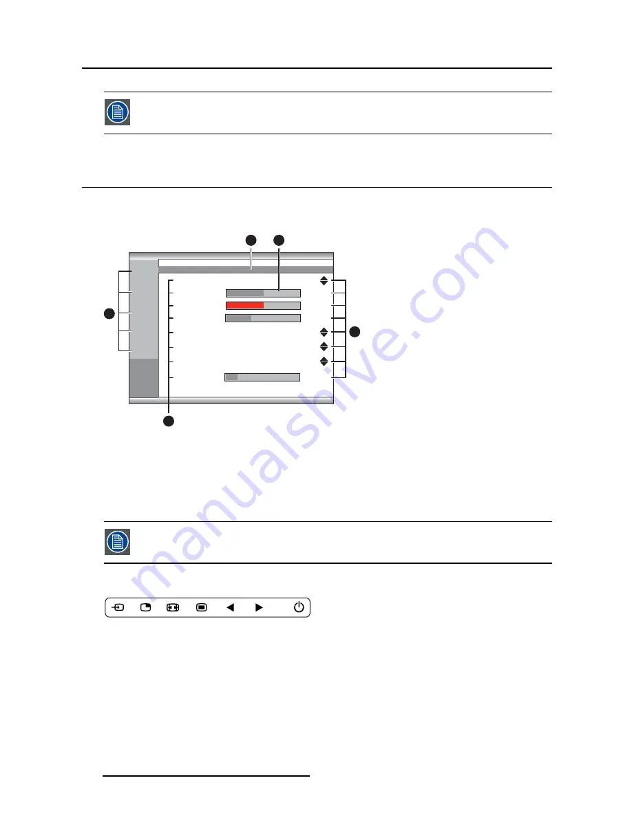
OSD menu structure explained

Below is an example of the OSD menu structure:

Picture

Brightness 


                   50 

Contrast  


                   50

Saturation 


                   30

Profile      

           Factory 

Color temperature           6500K

Gamma                                Native

Sharpness 


                   10

Color space                        ITU709

1

4

2

Picture

System

Input

select

Picture

advanced

Configuration

3

5

1024x768@100 Hz

Image 4-1

1. Menu pages
2. Sub-menus (menu items)
3. Status bar
4. Selector/Slider
5. Item

Grayed out menu items are not available on the speci

fi

c display version.

To navigate through the OSD menu

Image 4-2

18

K5902133 (451920612482) MDSC-8255 23/11/2017

Summary of Contents for MDSC-8255 MNA

Page 1: ...MDSC 8255 User Guide 55 inch UHD 4K surgical color display MDSC 8255 LED MDSC 8255 MNA K5902133 451920612482 01 23 11 2017 ...

Page 2: ... 26 22 62 Support www barco com en support Visit us at the web www barco com Registered address Barco NV President Kennedypark 35 8500 Kortrijk Belgium Phone 32 56 23 32 11 Fax 32 56 26 22 62 Support www barco com en support Visit us at the web www barco com Printed in Belgium ...

Page 3: ...llation 14 4 Daily operation 17 4 1 On Off switching 17 4 2 Power mode LED 17 4 3 OSD menu activation 17 4 4 OSD menu navigation 18 4 5 Shortkey functions 19 4 5 1 Main source selection 19 4 5 2 Brightness adjustment 19 4 6 OSD menu locking unlocking 20 5 Advanced operation 21 5 1 Picture menu 21 5 1 1 Profile 21 5 1 2 Brightness 21 5 1 3 Contrast 22 5 1 4 Saturation 22 5 1 5 Color temperature 22 ...

Page 4: ... 1 Power on DVI 31 5 5 2 Power on DisplayPort 31 5 5 3 OSD lock 31 5 5 4 Power saving 32 5 5 5 DVI output 32 6 Important information 33 6 1 Safety information 33 6 2 Environmental information 36 6 3 Biological hazard and returns 38 6 4 Maintenance 38 6 4 1 Cleaning and disinfection 38 6 4 2 Battery replacement 39 6 5 Regulatory compliance information 40 6 6 Explanation of symbols 40 6 7 Legal disc...

Page 5: ... Delivering image quality on large screens Color calibrated artifact free images in 4K resolution the MDSC 8255 presents surgeons with accurate realistic images and excellent depth perception Advanced video processing features and noise reduction algorithms and a full 10 bit image processing chain make this display ideal for consultation of any kind of medical referral images inside the OR Feature...

Page 6: ...during transport 1 3 About this user guide Overview This manual provides support to the user during the installation set up and utilization of the MDSC 8255 display Depending on the specific version that has been purchased some of the features and options described in this document may not apply to the display in user s hands 4 K5902133 451920612482 MDSC 8255 23 11 2017 ...

Page 7: ...ocated on the right side of the display 1 Input selection key 2 Multi image selection key Down key 3 Image zoom key Up key 4 OSD menu key Enter key 5 Brightness decrease Left key 6 Brightness increase Right key 7 Stand by key 8 Power mode LED 9 IR receiver for remote control future provision K5902133 451920612482 MDSC 8255 23 11 2017 5 ...

Page 8: ...unding 2 3 Connector view 2 3 1 MDSC 8255 LED version Overview 2 3 4 5 9 6 7 8 1 10 Image 2 3 1 SDI in 2 SDI out 3 USB 2 0 micro B interface 4 USB 2 0 type A interface 5 Main Right DisplayPort in 6 DVI D in 7 DVI D out 8 Potential Equalization pin POAG 9 2nd Left DisplayPort in 10 100 240 VAC 50 60 Hz power in 6 K5902133 451920612482 MDSC 8255 23 11 2017 ...

Page 9: ...ce 9 Identification button 10 SDI in 11 SDI out 12 Main Right DisplayPort in 13 DVI D in 14 DVI D out 15 Potential Equalization pin POAG 16 2nd Left DisplayPort in 17 100 240 VAC 50 60 Hz power in Input and Output 1 to 9 are directly connected to the embedded Nexxis decoder 2 4 Remote control Overview The remote control duplicates the functions of the keyboard and operates on an infrared IR based ...

Page 10: ...ey 3 Up key 4 Left key 5 Down key 6 Right key 7 OK Select key 8 Input selection key 9 Brightness increase key 10 Back key 11 Multi image selection key not supported 12 Brightness decrease key 2 5 Connector pin assignments 2 5 1 DVI connector DVI D Overview Image 2 6 8 K5902133 451920612482 MDSC 8255 23 11 2017 ...

Page 11: ...able sense 16 Hot plug detect 17 D0_Rx T M D S 18 D0_Rx T M D S 19 GND data 0 shield 20 Not connected 21 Not connected 22 GND clock shield 23 CK_Rx T M D S 24 CK_Rx T M D S 5 VDC output selectable on either pin 14 or 16 via the OSD menu 5V 10 500mA max 2 5 2 USB type A connector Overview Image 2 7 1 5 VDC 2 Data 3 Data 4 GND 2 5 3 Micro USB connector Overview 1 2 3 4 5 Image 2 8 1 5 VDC 2 Data 3 D...

Page 12: ... 10 8 6 4 2 Image 2 9 1 ML_Lane 0 p 2 GND 3 ML_Lane 0 n 4 ML_Lane 1 p 5 GND 6 ML_Lane 1 n 7 ML_Lane 2 p 8 GND 9 ML_Lane 2 n 10 ML_Lane 3 p 11 GND 12 ML_Lane 3 n 13 CONFIG1 14 CONFIG2 15 AUX CH p 16 GND 17 AUX CH n 18 Hot Plug 19 Return 20 DP_PWR 3 3 VDC 500 mA max 10 K5902133 451920612482 MDSC 8255 23 11 2017 ...

Page 13: ...ide the operating room and even between surgical suites To connect your MDSC 8255 to Barco s Nexxis OR system connect the 10Gb Ethernet interface to your Nexxis switch More info about Nexxis OR and how to configure the MDSC 8255 in your network is avail able in the dedicated user guides Please visit www barco com to obtain these user guides Nexxis OR is only available on the MDSC 8255 MNA version ...

Page 14: ...left of the screen Warning DisplayPort VESA DP 1 2 certified cables for 5 4 Gbps HBR2 are recommended 2 When the SDI video input is connected an additional SDI video sink can be connected to the SDI output SDI input loop through 3 Screen image clone The entire active image on the screen including OSD can be duplicated to a FHD 1080p 1080i signal on the DVI output connector to which an additional D...

Page 15: ...the proper power cord delivered with your display Main Main 1 2nd 2 2 Image 3 3 CAUTION The display must be earthed Potential equalization When potential equalization between the display and other devices is required then connect the potential equalization pin POAG to the potential equalization terminal of the equipment Main Main 1 2nd 2 2 Image 3 4 K5902133 451920612482 MDSC 8255 23 11 2017 13 ...

Page 16: ...e 3 5 3 3 VESA mount installation To install the display on a VESA mounting solution The display can be attached to a VESA 200 mm or VESA 600 mm arm or stand Image 3 6 The VESA mounting holes at the back of the display are provided with M6 type blind fasteners to fix the VESA mounting plate Depending on the VESA plate thickness T and the thickness of possible washers W a different screw length L s...

Page 17: ... is in compliance with VESA requirements CAUTION The monitor VESA interface has been designed for a safety factor 6 to sup port 6 times the monitor weight In the medical system use an arm with suitable safety factor IEC60601 1 K5902133 451920612482 MDSC 8255 23 11 2017 15 ...

Page 18: ...3 Display installation 16 K5902133 451920612482 MDSC 8255 23 11 2017 ...

Page 19: ... in power save mode backlight and LCD off Green amber blinking Searching for signal Note When Power save mode is enabled the display will automatically go into power save mode after 10 seconds of searching without signal Full green Display has a valid input signal 4 3 OSD menu activation To activate the OSD menu Press the key on the display As a result the OSD main menu comes up in the bottom righ...

Page 20: ... 50 Saturation 30 Profile Factory Color temperature 6500K Gamma Native Sharpness 10 Color space ITU709 1 4 2 Picture System Input select Picture advanced Configuration 3 5 1024x768 100 Hz Image 4 1 1 Menu pages 2 Sub menus menu items 3 Status bar 4 Selector Slider 5 Item Grayed out menu items are not available on the specific display version To navigate through the OSD menu Image 4 2 18 K5902133 4...

Page 21: ...resent a selection of commonly used functions immediately avail able without the need to navigate through the OSD menu The different available shortkey functions are Main source selection Brightness adjustment Overview of shortkeys 1 2 3 Image 4 3 1 Main source selection 2 Brightness decrease 3 Brightness increase 4 5 1 Main source selection To quickly select the main source Press the key to scrol...

Page 22: ... OSD lock window appear The OSD menu can only be accessed after pressing a sequence of keys To lock unlock the menu When the OSD lock window appears press the following key sequence to unlock the OSD menu Each time a key is pressed an asterisk is shown in the square boxes After pressing the fourth key if the sequence is correct the OSD main menu is activated After exit the OSD menu will automatica...

Page 23: ...able profiles for your display are Factory X Ray by selecting this profile Gamma and Color temperature will be automatically set to DICOM and Native respectively User 1 User 2 User 3 To select a profile 1 Bring up the OSD main menu 2 Navigate to the Picture menu 3 Enter the Profile submenu 4 Select one of the available profiles and confirm 5 1 2 Brightness To adjust the brightness level 1 Bring up...

Page 24: ...as desired and confirm 5 1 5 Color temperature About color temperature presets The available color temperature presets for your display are 5600K 6500K 7600K 9300K Native User Factory calibration White point The White Color points associated with the Color Temperature 5600K 6500K 7600K or 9300K are factory calibrated with a consequent reduction of the maximum luminance compared to Native Color Tem...

Page 25: ...cal limitation of the LCD panel used To select a color space preset 1 Bring up the OSD main menu 2 Navigate to the Picture menu 3 Enter the Color Space submenu 4 Select one of the available color space presets and confirm 5 1 7 Gamma About gamma presets The available gamma presets for your display are 1 8 2 2 2 4 Video transfer function adapted for video cameras with dark levels enhancement Native...

Page 26: ... the black level as desired and confirm 5 2 2 Latency About latency The video latency is defined as the delay between the time of a monitor input video transition to the cor responding light output transition on screen The available latency modes for your display are Diagnostic Best picture quality Surgical Lowest latency optimized for fast moving images To select the latency mode 1 Bring up the O...

Page 27: ...ntally making the left content appear on the right and vice versa Rotation rotates the image 180 When image rotation is selected the latency will increase with 20 msec Image mirroring does not cause any latency increase To enable disable horizontal flip 1 Bring up the OSD main menu 2 Navigate to the Picture Advanced menu 3 Enter the Image Flip submenu 4 Select one of the available options and conf...

Page 28: ...D main menu 2 Navigate to the Input Select menu 3 Enter the DP mode submenu 4 Select one of the available DisplayPort modes and confirm 5 3 3 Auto search About auto search By enabling the input selection auto search function the display will automatically detect the connected source and display it on the screen To enable disable auto search 1 Bring up the OSD main menu 2 Navigate to the Input Sele...

Page 29: ...The main source can be changed while the failover input remains unchanged During the selection and synchronization of a new main source the failover function is temporary 7 sec disabled To select the failover input 1 Bring up the OSD main menu 2 Navigate to the Input Select menu 3 Enter the Failover Input submenu 4 Select one of the available failover inputs and confirm 5 3 5 2nd Picture Mode Abou...

Page 30: ...picture sources and confirm 5 4 Configuration menu 5 4 1 Information About information The available information items for your display are Model commercial type identification Operating Hours unit operation hours Main board release hardware and firmware identification MNA release firmware identification Eth1 Main IP address of Main ethernet 1 port of the monitor Eth2 2nd IP address of 2nd etherne...

Page 31: ...rce shortkey 1 Bring up the OSD main menu 2 Navigate to the Configuration menu 3 Enter the Source shortkey submenu 4 Enable Disable the main source shortkey as desired and confirm 5 4 4 OSD setting 5 4 4 1 OSD Horizontal Position To adjust the OSD horizontal position 1 Bring up the OSD main menu 2 Navigate to the Configuration menu 3 Enter the OSD setting submenu 4 Select OSD Hor Pos The command b...

Page 32: ...y and X Ray profiles or recall the user defined profiles The available profiles to recall from your display are Factory X Ray User 1 User 2 User 3 To recall a profile 1 Bring up the OSD main menu 2 Navigate to the Configuration menu 3 Enter the Recall Profile submenu 4 Select one of the available profiles to recall and confirm 5 4 6 Save Profile About saving profiles The user can modify the defaul...

Page 33: ...enu 4 Select one of the available options and confirm 5 5 2 Power on DisplayPort About power on DisplayPort This setting allows you to select if the 3V3 DC supply is applied on the DisplayPort connector or not The available options are Disabled 3V3 on DP main To select the power on DisplayPort 1 Bring up the OSD main menu 2 Navigate to the System menu 3 Enter the Power on DP submenu 4 Select one o...

Page 34: ...arch page 26 the display will not enter the power save mode even when the input s is are missing To enable disable power saving 1 Bring up the OSD main menu 2 Navigate to the System menu 3 Enter the Power Saving submenu 4 Enable Disable power saving as desired and confirm 5 5 5 DVI output About DVI output This setting allows to enable or disable the DVI output function of your display Enabling DVI...

Page 35: ... once a year Type of protection Electrical Equipment with external power supply Class I equipment Degree of safety flammable anesthetic mixture Equipment not suitable for use in the presence of a flammable anesthetic mixture with air or with oxygen or nitrous oxide Non patient care equipment Equipment primarily for use in a health care facility that is intended for use where contact with a patient...

Page 36: ...nt MDSC 8255 MNA version only Connection of the PEMS to a network data coupling that includes other equipment could result in previously unidentified risks to patients operators or third parties The responsible organization should identify analyze evaluate and control these risks Subsequent changes to the network data coupling could introduce new risks and require additional analysis Changes to th...

Page 37: ...and usage The manufacturer is not liable for any damage or injury caused by mishandling or improper installation Malfunctions Disconnect the equipment s power cord from the AC inlet and refer servicing to qualified service techni cians under the following conditions If the power cord or plug is damaged or frayed If liquid has been spilled into the equipment If the equipment has been exposed to rai...

Page 38: ...t this product must not be disposed of with other municipal waste Please dispose of your waste equipment by handing it over to a designated collection point for the recycling of waste electrical and electronic equipment To prevent possible harm to the environment or human health from uncontrolled waste disposal please separate these items from other types of waste and recycle them responsibly to p...

Page 39: ...at this toxic or hazardous substance contained in all of the homogeneous materials for this part is below the limit requirement in GB T 26572 X 表示该有毒有害物质至少在该部件的某一均质材料中的含量超出 GB T 26572 标准规定的限量要求 X Indicates that this toxic or hazardous substance contained in at least one of the homogeneous materials used for this part is above the limit requirement in GB T 26572 在中国大陆销售的相应电子信息产品 EIP 都必须遵照中国大陆 电子电气产...

Page 40: ...ion process as defined in the latest edition of the ANSI AAMI ST35 standard on each single failed Product that is returned for servicing repair reworking or failure investigation to Seller or to the Authorized Service Provider At least one adhesive yellow label shall be attached on the top site of the package of returned Product and accompanied by a declaration statement proving the Product has be...

Page 41: ...ontrol or its range seems to be reduced it may be time to replace the battery Follow the steps below to replace the battery 1 Insert a coin in the battery cover slot on the back of the remote control an turn it counterclockwise 2 Remove the used battery and replace it with a new battery CR2032 with the plus symbol facing up 3 Replace the cover and turn the cover slot clockwise until it locks into ...

Page 42: ...an radiate radio frequency energy and if not installed and used in accordance with the instructions may cause harmful interference to radio communications However there is no guarantee that interference will not occur in a particular installation If this device does cause harmful interference to radio or television reception which can be determined by turning the device off and on the user is enco...

Page 43: ... the BSMI regulations Indicates the device is approved according to the PSE regulations Indicates the device is approved according to the RCM regulations Indicates the device is approved according to the EAC regulations Caution Federal law United Stated of America restricts this device to sale by or on the order of a licensed healthcare practitioner Indicates the device is approved according to th...

Page 44: ...an WEEE Waste Electrical and Electronic Equipment directive Indicates Direct Current DC Indicates Alternating Current AC Stand by Equipotentiality or Protective earth ground Symbols on the box On the box of the device you may find the following symbols nonrestrictive list Indicates a device that can be broken or damaged if not handled carefully when being stored Indicates a device that needs to be...

Page 45: ...t we assume no responsibility for errors that may be found Our goal is to provide you with the most accurate and usable documentation possible if you discover errors please let us know Barco software products are the property of Barco They are distributed under copyright by Barco NV or Barco Inc for use only under the specific terms of a software license agreement between Barco NV or Barco Inc and...

Page 46: ...L 9003 Screen protection 2 side anti reflective alkali aluminosilicate glass no screen protection on NG versions Keyboard Membrane keyboard 4K UHD input 1x DP 1 1 up to 3840 x 2160 30Hz 2x DP 1 1 up to 1920 x 2160 50Hz 60Hz 1x DP 1 2 MST up to 3840 x 2160 50Hz 60Hz Video input signals FHD input upscaled to UHD 1x DVI 1x 3G SDI 1x 3G SDI 3G SDI input loopthrough Video output signals 1x DVI image on...

Page 47: ...60601 1 2006 A1 2013 Medical electrical equipment Part 1 General requirements for safety Electromagnetic Compatibility EMC Medical EMC Standards IEC60601 1 2 4th Ed EN55011 CISPR 11 FCC CFR47 part 15 18 Class B Approvals Marking CE c UL us DEMKO KCC CCC ROHS 2 REACH WEEE CEL compliant Operating temperature 0 35 C for performance 0 40 C for safety Storage temperature 20 60 C Operating humidity 10 9...

Page 48: ...tream DP 1 1 10 bit up to 1920x2160 x2 60Hz RGB 30bits pixel 3G SDI 10 bit in compliance with SMPTE 425M Level A SMPTE 424M SMPTE 292M SMPTE 259M SMPTE 296M ITU R BT 656 ITU R BT 601 DVI 8 bit up to 1920x1080 60Hz RGB 24bits pixel Integrated Nexxis 4k decoder MNA 240 decoder integrated Remote control FW download control protocol through network connection IR remote control Power consumption nomina...

Page 49: ...ical equipment Part 1 General requirements for basic safety and essential performance EN 60601 1 2006 A1 2013 Medical electrical equipment Part 1 General requirements for safety Electromagnetic Compatibility EMC Medical EMC Standards IEC60601 1 2 4th Ed EN55011 CISPR 11 FCC CFR47 part 15 18 Class B Approvals Marking CE c UL us DEMKO KCC CCC ROHS 2 REACH WEEE CEL compliant Operating temperature 0 3...

Reviews: