background image

Doc No: 26-1803004-00 /01

ENABLING BRIGHT OUTCOMES

Barco Technical Support:
USA:


+1 (866) 374-7878

EMEA:


+32 (56) 36 8019

CHINA:


40088 22726

www.barco.com/en/support

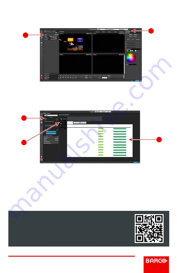
Multiviewer (MVR)  Menu

(Continued)

M2

: Adjust Window – Adjust the size, position and the color parameters associated 

with each window. Repeat for all Inputs and save.

S1

: Options – On the Options tab click on the boxes to select system wide user 

preferences such as Layer positioning.

Settings  Menu

S3

: Dashboard – Provides status information regarding the cards and other system 

diagnostic information.

S2

: Tools – Allows users to perform Backup and Restore operations or download 

the latest software from the Barco website.

Multiviewer (MVR) Menu

M2

M1

Settings Menu

Dashboard

a quick glance of your E2

Expansion

0

Ready

Run Diagnostics 

Expansion

1

Ready

Run Diagnostics 

Input

2

Ready

Run Diagnostics 

Input

3

Ready

Run Diagnostics 

Input

4

Ready

Run Diagnostics 

Input

5

Ready

Run Diagnostics

Input

6

Ready

Run Diagnostics 

Input

7

Ready

Run Diagnostics 

Input

8

Ready

Run Diagnostics 

Input

9

Ready

Run Diagnostics 

Input

10

Ready

Run Diagnostics 

Expansion

Slot ID

Card Status

Actions

Inputs

Outputs

Other

S3

S1

S2

Page 8 of 8

Summary of Contents for E2 Gen 2

Page 1: ...ice 8 ADJUST knob 9 SEL and ESC buttons 10 Power switch 7 Display 6 USB port MVR MVR 5 3 1 2 4 7 6 8 10 9 1 Inputs 2 Multiviewers 3 PC with Event Master control software 5 Outputs 4 Ethernet switch Do...

Page 2: ...reset For a continuing or multi day event this step is not required System Initialization Restoring the System Optional Insert a USB drive with a previous backup file into the USB Port On the Backup...

Page 3: ...2 connector Formats up to 4096x2160 60 30 bits 4K UHD supported HDCP 1 3 EDID 1 3 1 HDMI 2 0 connector Formats up to 2560x1600 60 and 3840x1200 60 30 bits 4K UHD supported HDCP 1 4 and 2 2 compatible...

Page 4: ...ble until it locks in place 1 Connect the Link cables provided with each E2 between the Link connectors as follows VP ID 0 Link Card slot 1 Link 1 VP ID 1 Link Card slot 1 Link 2 VP ID 0 Link Card slo...

Page 5: ...MVR Outputs C8 Add Screen Destinations Add Layers to Destinations C9 Add Aux Destinations P2 Select thumbnails for Inputs P3 Create Sources from Inputs P5 Drop Layers into Screen Destinations Sources...

Page 6: ...n Menu ensure that the IP settings match with the E2 settings that are available from the front panel You can also connect to the E2 by typing the IP address manually C3 System Parameters Select the d...

Page 7: ...put Background and drop it to the Aux Destinations Select the Adjust tab and perform any additional adjustments Repeat for all Backgrounds and save P7 User Keys Select a layer and under Adjust and Use...

Page 8: ...on regarding the cards and other system diagnostic information S2 Tools Allows users to perform Backup and Restore operations or download the latest software from the Barco website Multiviewer MVR Men...

Reviews: