


8. Input menu
Genlock off
(default position) locking done on input source of main window, when automatic was selected or on the
selected input source when a speci
fi
c input was selected. Projector detects automatically the vertical
frequency and clock frequency of the input signal. A slightly difference with the source is possible.
Genlock on
locking done on indicated vertical frequency and clock frequency. This vertical frequency and clock frequency
must be exactly the same as those of the source.
Only use genlock ON for very stable sources and preferable for broadcast sources.
For Genlock on,
to change the locking frequency, use the
▲
or
▼
key to select
Vert freq
and press
ENTER
to activate. The
fi
rst digit is selected.
Use the
▲
or
▼
key to select the desired digit and press
◄
or
►
key to select the next digit in the address or enter the value with
the digit keys on the remote control or local keypad. The next digit in the value will be automatically selected.
to change the clock frequency, use the
▲
or
▼
key to select
Clock freq
and press
ENTER
to activate. The
fi
rst digit is selected.
Use the
▲
or
▼
key to select the desired digit and press
◄
or
►
key to select the next digit in the address or enter the value with
the digit keys on the remote control or local keypad. The next digit in the value will be automatically selected.
For older custom
fi
les, created with software packages older than package 1.5.6, the Genlock function will
be grayed out. If you want to use this genlock function, a new custom
fi
le must be created starting from the
standard
fi
le. Copying the custom
fi
le in a new
fi
le do not solve this issue.
8.4
Minimum delay
Purpose
In normal mode, the processing (scaling and de-interlacing) in DLP projectors introduces a few frames delay (from input to screen).
Setting the option
Minimum Delay
to "ON" disables all scaling and de-interlacing in the processing and reduces frame delay of the
projector (from input to screen) to ONE frame, caused by the formatter board (DLP technology restriction). The intended use of this
option is to apply native and progressive data to the projector and displaying it with minimum delay, using the full resolution of the
projector. Other formats will be displayed either unscaled and/or interlaced.
This feature can be used if additional delay in the projector is not acceptable. For instance if a projector is showing the DVI loop out
of another DLP or if an external scaler/de-interlacer does the processing.
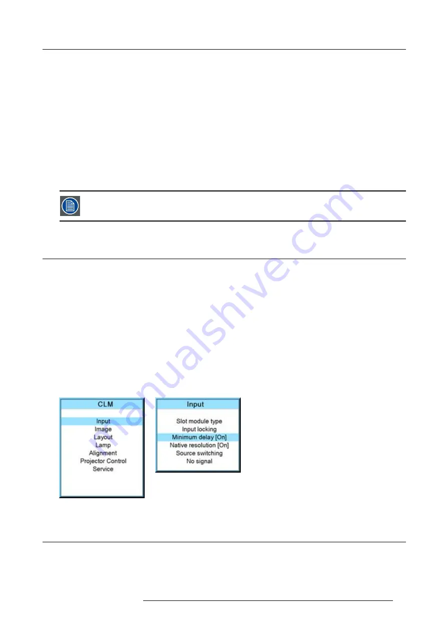
How to toggle the delay?
1. Press
MENU
to activate the menus.
2. Use the
▲
or
▼
key to select
Input
and press
ENTER
.
The Input menu is displayed.
3. Use the
▲
or
▼
key to select
Minimum delay
and press
ENTER
to toggle between [On] and [Off]. (image 8-11, image 8-12)
Image 8-11
Image 8-12
8.5
Native resolution
What can be done
The aim here is to always show the resolution of the source independently of the resolution of the DMD panels.
R59770021 CLM R10+ 11/10/2010
67
Summary of Contents for CLM R10+
Page 1: ...CLM R10 Users manual R9050100 R90501001 R90501005 R59770021 11 11 10 2010 ...
Page 14: ...1 Safety 10 R59770021 CLM R10 11 10 2010 ...
Page 22: ...2 General 18 R59770021 CLM R10 11 10 2010 ...
Page 36: ...3 Physical installation 32 R59770021 CLM R10 11 10 2010 ...
Page 41: ...4 Stacking CLM projectors Zoom Image 4 9 Zoom adjustment R59770021 CLM R10 11 10 2010 37 ...
Page 42: ...4 Stacking CLM projectors 38 R59770021 CLM R10 11 10 2010 ...
Page 50: ...5 Connections 46 R59770021 CLM R10 11 10 2010 ...
Page 66: ...7 Start up of the Adjustment mode 62 R59770021 CLM R10 11 10 2010 ...
Page 75: ...8 Input menu Image 8 26 Image 8 27 Image 8 28 R59770021 CLM R10 11 10 2010 71 ...
Page 76: ...8 Input menu 72 R59770021 CLM R10 11 10 2010 ...
Page 102: ...9 Image menu 98 R59770021 CLM R10 11 10 2010 ...
Page 169: ...14 Service menu Image 14 55 Image 14 56 Image 14 57 R59770021 CLM R10 11 10 2010 165 ...
Page 170: ...14 Service menu 166 R59770021 CLM R10 11 10 2010 ...
Page 184: ...16 Servicing 180 R59770021 CLM R10 11 10 2010 ...
Page 194: ...17 Projector covers removal and installation 190 R59770021 CLM R10 11 10 2010 ...
Page 202: ...C DMX Chart 198 R59770021 CLM R10 11 10 2010 ...
Page 212: ...E Troubleshooting 208 R59770021 CLM R10 11 10 2010 ...
Page 218: ...F Mounting optional Carry handle 214 R59770021 CLM R10 11 10 2010 ...
Page 220: ...G Order info 216 R59770021 CLM R10 11 10 2010 ...


