5. Getting Started
6. Push the cursor key
↑
or
↓
to highlight
Highlighted item color
.
7. Press
ENTER
to toggle between red, green and yellow.
ADJUSTMENT MODE
Select a path from below :
RANDOM ACCESS
INSTALLATION
SERVICE
Select with
↑
or
↓
then <ENTER>
<EXIT> to return
Menu 5-5
INSTALLATION
INPUT SLOTS
800 PERIPHERAL
SOURCE SWITCHING
NO SIGNAL
CONTRAST ENHANCEMENT
CONVERGENCE
CONFIGURATION
LENS
QUICK ACCESS KEYS
OSD
INTERNAL PATTERNS
Select with
↑
or
↓
then <ENTER>
<EXIT> to return
Menu 5-6
OSD
HIGHLIGHT ITEM COLOR [red]
MENU POSITION [Default]
Select with
↑
or
↓
then <ENTER>
<EXIT> to return
Menu 5-7
5.5 Using the RCU
Pointing to the reflective screen
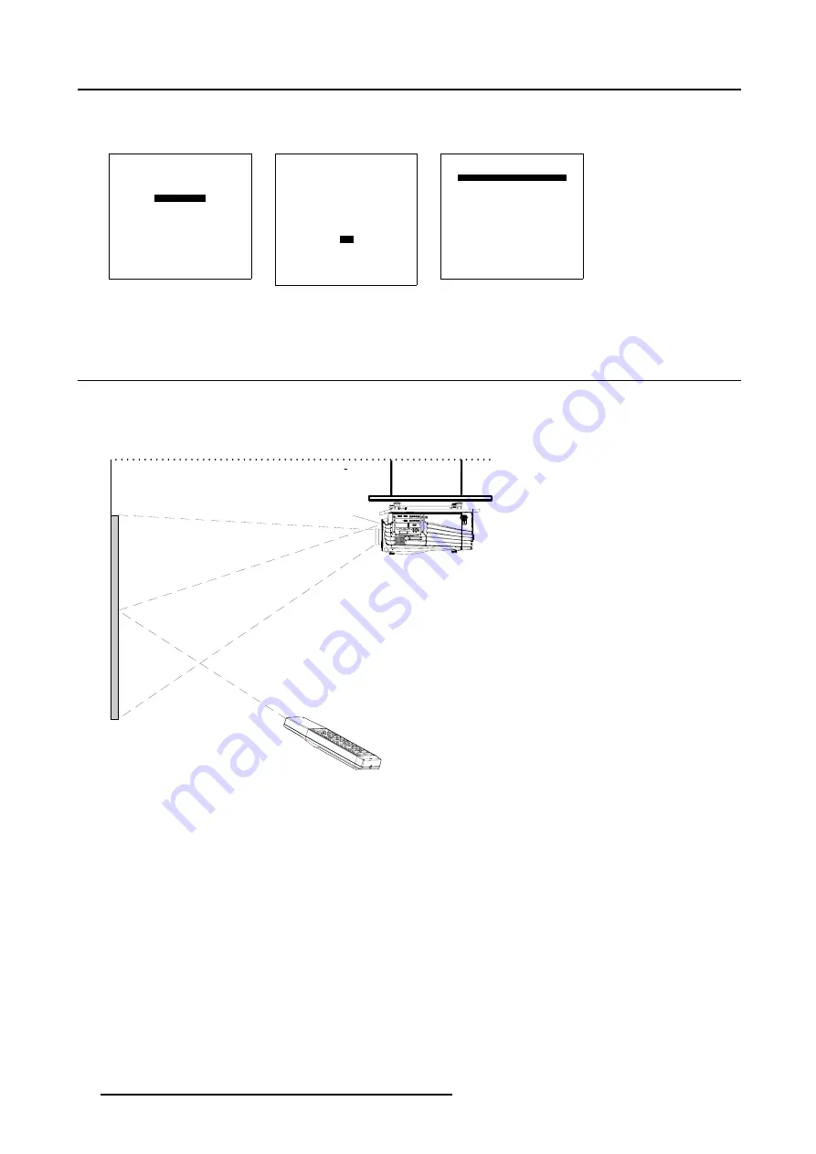
1. Point the front of the RCU to the reflective screen surface. (image 5-5)
Ceiling
Screen
IR sensor
RCU
Image 5-5
Hardwired Remote Input
1. Plug one end of the remote cable in the connector on the bottom of the RCU.
2. Plug the other end in the connector in the front panel of the projector labelled
RC
. (image 5-6)
50
R5976562 BARCOSLM G10 PERFORMER 20/10/2004
Summary of Contents for BarcoSLM G10 Performer
Page 1: ...BarcoSLM G10 Performer Owners Manual R9010000 R5976562 03 20 10 2004 ...
Page 4: ......
Page 8: ...Table of contents 4 R5976562 BARCOSLM G10 PERFORMER 20 10 2004 ...
Page 14: ...2 Packaging and Dimensions 10 R5976562 BARCOSLM G10 PERFORMER 20 10 2004 ...
Page 34: ...3 Installation Guidelines 30 R5976562 BARCOSLM G10 PERFORMER 20 10 2004 ...
Page 92: ...7 Random Access Adjustment Mode 88 R5976562 BARCOSLM G10 PERFORMER 20 10 2004 ...
Page 124: ...10 Programmable Function Keys 120 R5976562 BARCOSLM G10 PERFORMER 20 10 2004 ...
Page 128: ...A Standard Source set up Files 124 R5976562 BARCOSLM G10 PERFORMER 20 10 2004 ...


