background image

10

AUSTAUSCH DES VERSORGUNGSKABELS

 Falls notwendig, kann das Netzkabel durch 

ein  anderes  gleicher  Art  ersetzt  werden

(siehe 

“Technische  Daten”  auf  S.  4)

das  den  gültigen 

Bestimmungen des Landes entspricht, in dem das 
Gerät installiert wird.

 Wenn  das  Gerät  bereits  angeschlossen 

ist, muss es von der Stromversorgung getrennt 
werden.

Die elektrischen Anschlüsse sind bei Entfernen des 
Deckels der Klemmenleiste durch Lösen der Befesti-
gungsschraube zugänglich 

(Abb. 4)

.

Das alte Kabel von den Klemmen trennen und her-
ausnehmen; das neue Kabel (ausschließlich vom Typ 

H05V2V2-F

) an die Klemmen N - L - Erde anschließen. 

Das  neue  Kabel  mit  dem  Kabelhalter  befestigen 
und  die  Klemmenleiste  wieder  mit  ihrem  Deckel 
abschließen.

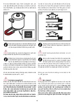
L3

2x 230 V + N + PE

L2

L1

N1

N2

L1

L1

L2

L2

L1

L1

N

N

2x 230 V + PE

1x 230 V + N + PE

4

POWER CORD REPLACEMENT

  If necessary, the power cord can be replaced 

with an identical type 

(see “Technical data” on page 

4) 

in  compliance  with  current  regulations  in  the 

country where the appliance is installed.

  If the appliance is already connected, discon-

nect the electrical power.

To access the electrical connections, remove the cover 
from  the  terminal  board  by  unscrewing  the  screws 

(figure 4)

.

Disconnect the old cord from the terminals and remove 
it; connect the new cord (only the 

H05V2V2-F

 type) into 

the respective terminals N - L - Earth. 
Cover the new cord with the appropriate cord holder and 
re-close the terminal, replacing its cover.

Summary of Contents for ASPBIR140

Page 1: ...ASPBIR930 ASPBIR140 taste of design Lab Evolution Induzione Installations und Gebrauchsanleitung Installation and use manual ...

Page 2: ...eser Gebrauchsanleitung vorzunehmen die er für notwendig hält ohne dass daraus eine Verpflichtung zur Vorankündigung entsteht DieinderAnleitungenthaltenenZeichnungen Installationspläne undTabellengeltenalsRichtangabenundfürInformationszwecke Die Anlagen für den Energieanschluss des Geräts müssen den gültigen nationalen Vorschriften entsprechen Es ist verboten diese Gebrauchsanleitung zu kopieren i...

Page 3: ...2 Regelmäßige Pflege 22 Reinigung 22 Stillstandszeiten 23 Entsorgung am Ende der Nutzungsdauer 24 Kundendienst 24 DESCRIPTION PAGE TECHNICAL DATA 4 INSTALLATION 5 Safety warnings 5 Checks and handling 6 Disposal of the packaging 6 Installation site choice 7 Connection to the power mains 8 Built in unit installation 11 USAGE 13 Safety warnings 13 Before starting 15 Understanding the appliance 15 Co...

Page 4: ... OCTA 210X190 OCTA 210X390 bridge Power zone OCTA 210X190 OCTA 210X390 bridge kW kW 2 1 3 0 1 5 1 85 Kabeltyp Cable type H05V2V2 F 3x1 5 mm2 Kabellänge Cable length cm 90 Abmessungen des Geräts Appliance dimensions Breite Width cm 88 Tiefe Depth cm 51 Gesamthöhe Enclosure height cm 6 8 mm ASPBIR930 90 90 510 880 850x480 67 R 6 Insulating class 1 1 L 90cm With custom made models dimensions are made...

Page 5: ... 6 2 0 2 8 kW 3 5 4 3 5 0 kW 5 5 6 0 7 4 Zonenleistung OCTA 210x190 OCTA 210x390 bridge Power zone OCTA 210x190 OCTA 210x390 bridge kW kW 2 1 3 0 1 5 1 85 Kabeltyp Cable type H05V2V2 F 3x1 5 mm2 Kabellänge Cable length cm 90 Abmessungen des Geräts Appliance dimensions Breite Width cm 116 Tiefe Depth cm 51 Gesamthöhe Enclosure height cm 6 8 ASPBIR140 mm 120 120 510 1160 67 1130x480 R 6 ...

Page 6: ...ALLATION SICHERHEITSHINWEISE Lesen Sie diese Gebrauchsanleitung aufmerksam durch bevorSiedasGerätinstallierenbzw benut zen Diese Gebrauchsanleitung muss an einem für alle Benutzer zugänglichen Ort aufbewahrt werden Bei Verkauf oder Weitergabe des Geräts muss sie dem neuen Benutzer übergeben werden damit er Kenntnis von der Installation dem Gebrauch und den Sicherheitsvorschriften erhält Die Instal...

Page 7: ...osition cardboard polyethylene polypropylene outer packaging film instructions bag KONTROLLE UND HANDHABUNG Nach dem Auspacken des Geräts müssen alle Ver packungsmaterialien und die Schutzfilme von der Oberfläche beseitigt werden Kontrollieren Sie ob sichtbare Fehler vorhanden sind Wenn ja installieren Sie den Ofen nicht sondern verständigen Sie Ihren Händler binnen 8Tagen unter Angabe der Daten d...

Page 8: ...rd sind deren Montageanleitungen zu beachten indenendieeinzuhaltenderichtigeDistanz angegeben ist C A min 3 5 cm B min 4 5 cm C min 56 cm A B 2 INSTALLATION SITE CHOICE Installation site characteristics The appliances must be placed in suitable interior loca tionswithamaximumtemperatureof25 Candmaximum humidity of 60 the locations must satisfy the safety standards in force in the country of use pr...

Page 9: ...rden mit Verlängerungen verwendet werden H05V2V2 F 3x1 5mm2 90 cm 16A B A Mod Art N V Hz Kw Questo apparecchio deve essere installato conformemente alle norme in vigore Consultare il libretto istruzioni prima di installare e usare l apparecchio F lli Barazza S r l MADE IN ITALY 3 CONNECTION TO THE POWER MAINS Beforemakingtheconnection makecertain that the voltage and frequency indicated on the dat...

Page 10: ...ßen Das neue Kabel mit dem Kabelhalter befestigen und die Klemmenleiste wieder mit ihrem Deckel abschließen L3 2x 230 V N PE L2 L1 N1 N2 L1 L1 L2 L2 L1 L1 N N 2x 230 V PE 1x 230 V N PE 4 POWER CORD REPLACEMENT Ifnecessary thepowercordcanbereplaced withanidenticaltype see Technicaldata onpage 4 in compliance with current regulations in the country where the appliance is installed Iftheapplianceisal...

Page 11: ... empfohlen Lüftungsausschnitte anzubringen Abb 5 11 mm Incasso Built in Filo Flush 1 2 1 1 mm mm 860 490 513 883 860 490 R 7 5 mm 90 90 120 120 1140 490 513 1163 1140 490 R 7 5 5 BUILT IN UNIT INSTALLATION Make certain that the cabinet in which you willbeinstallingtheapplianceisinperfectcondition and completely stable Standard DIN 68930 Prepareanembeddedholewithmeasurementsasspecified infigure5 if...

Page 12: ...aterial Abb 6A Teil 4 EINBAUKOCHFELDER SetzenSiedasGerätaufdieEinbaunischeunddrücken Sie es gegen die Arbeitsplatte Abb 6B Teil 1 Befestigen Sie das Gerät mit den mitgelieferten Schrauben und Klammern Abb 6B Teil 2 FLUSH PANELS Arrangetheapplianceabovetheembeddedhole figure 6A part 1 secure it using the screws and brackets pro vided figure 6A part 2 Seal the gap between the panel and lowering with...

Page 13: ...emitdemGerätodermitTeilendesGerätsspielen VerwendenSiekeineSpraysinderNähedieses Geräts wenn es in Betrieb steht Dieses Gerät darf nicht geändert werden USAGE SAFETY WARNINGS FOR SAFE AND CORRECT USE This appliance has been designed and manufac turedexclusivelyforcookingfood Anyotheruseisconsid eredimproperandthuspotentiallyhazardousforpeople animals and property Furthermore it may permanently dam...

Page 14: ...icht einfach die Topferkennung Treffen Sie beim Kochen alle nur möglichen Vorsichtsmaßnahmen um die Kochplatte nicht zu zerkratzen Fire hazard Do not use the appliance as a support surface The area near the appliance may become very hot so take precautions when positioning power outlets other household appliances electrical cables hoses and any heat sensitive or flam mable material in this area Ov...

Page 15: ...egeben Am Anfang könnte das neue Gerät Rauch oder unangenehmen Geruch erzeugen was auf die Ver brennung von Fetten zurückzuführen ist die bei der Herstellung verwendet werden Sorgen Sie in diesem Fall für die Lüftung des Raums BEFORE STARTING UNDERSTANDING THE APPLIANCE Inductioncookingzonesareequippedwithspecial inductioncoilsinordertogenerateamagneticfield whichisdirectlytransferredtoironcompone...

Page 16: ...LD Zur Bestimmung welcher Drehschalter welche Kochzone steuert ist der Aufdruck in Schalternähe zu beachten der klar und eindeutig festlegt welche Zone dem Schalter zugeordnet ist Abb 8 8 POWER MANAGEMENT The induction hobs are equipped with power manage ment Thankstothisfunction youcansetthemaximum power that the hob can absorb preventing any risk of overload Model 90 Power kW 1 6 2 0 2 8 3 5 4 3...

Page 17: ...Kontrollieren ob ein Magnet am Geschirrboden haftet Abb 11 2 Kontrollieren ob das Symbol am Geschirr boden vorhanden ist Carefully select food containers with the most energy saving benefits All pans pots made of iron steel enamel and cast iron may be used in the induction cooking process In order to check the suitability of pans pots please see the following two methods 1 check that a magnet stic...

Page 18: ...ertra gene Wärme spürbar Achten Sie darauf diesen Bereich nicht zu berüh ren wennSiedenTopfvonderKochzonenehmen In order to ensure the even distribution of heat across thesurface the base of the pot pan must be completely flat inaddition inordernottoscratchtheglass ceramic surface the base must also be smooth figure 12 OK 12 Heating will only initiate when a food container suited to the induction ...

Page 19: ...e Töpfe zum Kochen verwendet werden sollen z B Auflaufformen Pfannen Zum Aktivieren dieser Funktion müssen die beiden Drehschalter gleichzeitig im Uhrzeigersinn über die Be grenzung hinaus gedreht werden Das Display zeigt die Symbole zurAngabe dassdieFunktionaktiviertist SPECIAL FUNCTIONS AUTOMATIC PRE HEATING FUNCTION This function provides pre heating of the cooking zone at maximum power so that...

Page 20: ...as betreffende Display das Symbol an Restwärme Diese Anzeige erlischt erst dann wenn keineVerbren nungsgefahr mehr besteht Thepowerofthebridgecookingzonecanonlybeadjusted using the knob for the front cooking zone Todeactivatethefunction changethepositionoftheknob for the rear cooking zone CONTROL PANEL LOCK FUNCTION The controls can be locked to avoid accidental activation e g by children during c...

Page 21: ...leiner als für das Gerät zulässig 3 Am Kochfeld ist kein Kochgeschirr vorhanden POT DETECTION In the instance where the symbol appears on one of the cooking zone display it signifies that 1 theinstrumentusedisnotsuitedforinductioncooking 2 the diameter of the instrument used is smaller than that which is recommended to be used with the appli ance 3 there is no instrument present on the surface ...

Page 22: ...ieeinenmitneutralem Reinigungsmittel leicht befeuchteten weichen Lappen für dieVerwendung der Reinigungsmittel sind die Anleitungen ihres Herstellers zu befolgen WARTUNG SAFETY WARNINGS Alwaysdisconnecttheappliancefromthepower supplyandandremovetheconnectionplugfromthesock etbeforecarryingoutanycleaningoperationsorwhenthe appliancewillnotbeusedforanextendedperiod Regularlycheckthattheelectricalcab...

Page 23: ... nehmen Sie eine sorgfältige Reinigung nach den Angaben im betreffenden Kapitel vor ziehen Sie den Netzstecker ab Ensure that the detergent has not remained lodged under the knob Ensure that upon finishing the cleaning of the knob it has not been accidentally moved from the 0 off position Glass ceramic surfaces Useful information on the material Glass ceramic surfaces are extremely heat resistant ...

Page 24: ... verwendet werden Bei Verwendung anderer Bauteile als jener die vom Hersteller geliefert werden verfällt die Garantie und Personen sowie Geräteschäden können verur sacht werden END OF LIFE DISPOSAL Thecrossedbinsymbolontheproductindi cates that the waste arising from electrical and electronic equipment WEEE must be handled separately from undifferentiated waste sothatitcanundergospecialopera tions...

Page 25: ...Hinweise ...

Page 26: ...26 Hinweise ...

Page 27: ...27 ...

Page 28: ...estaltung Artlinea Cod PLAEI_00_2 Rev 00 01 2022 Barazza srl 31025 Sarano di S Lucia di Piave TV ITALIA Via Risorgimento 14 Tel 39 0438 62888 Fax 39 0438 64901 info barazzasrl it www barazzasrl it taste of design ...

Reviews: